





Lubomír Zeman: Thermoplastic injection molding technology and weight reduction of injection moldings, part 4
PREREQUISITES FOR WEIGHT REDUCTION – MANUFACTURING DESIGN OF THERMOPLASTIC INJECTION MOLDED PARTS
Manufacturing design of thermoplastic injection molded parts – the term "manufacturing design" covers one of the most important requirements for the properties of plastic parts. Without fulfilling the requirements contained in this term, it is not possible to work with the prerequisites mentioned in previous chapters, i.e., the prerequisites for reducing the weight of parts through the appropriate choice of material and injection molding technology.
Manufacturing design is based on the quality requirements placed on a molded part by its user and is the second step in the pre-production stages for the manufacturing of thermoplastic parts with defined customer quality parameters, where the pre-production stages include:
- definition of requirements for the molded part
- design and engineering of the part – according to the principles of manufacturing design for thermoplastic injection molded parts
- selection of material to meet the requirement for minimizing the weight of the part
- selection of injection molding technology from the perspective of producing the part with minimum weight
- moldability analysis
- simulation calculations
- modification of the part design based on comments arising from previous steps
- production of the part using one of the Rapid Prototyping technologies
- production of the prototype mold and prototype parts, including its evaluation and possible modifications
In the case of carrying out the steps of the pre-production stages, it is necessary to keep in mind that if we release, or accept into production, serial molds and parts from them, a poorly specified part – its design, material, quality requirements – nothing will stop us from producing parts that will not meet the specified quality requirements.
From the perspective of minimizing the weight of molded parts, the most important design element of the part is its ribbing – the design of the ribs. Let us therefore ask the question – why is it advantageous to design thermoplastic parts with ribs? The answer is simple – the part will have a reduced weight, the production cycle time will be shortened, and this while maintaining the mechanical properties of the part as if it were a solid material. The stated finding is documented in Figure 11.
 |
A – solid part - part design without respecting the principles of manufacturing design – the part has a second moment of area of 2,520 mm2 and the holding time was 95 s = 100 %, material = 100 %
B – ribbed part – variant 1 – second moment of area 2,520 mm2, reduction of holding time to 35 %, material savings of 23 %
C – ribbed part, variant 2 – second moment of area 2,520 mm2, reduction of holding time to 15 %, material savings of 57 %
 |
A – correct ratio of rib thickness and the radius of its connection to the base wall of the part
B – excessively large radius – increased material consumption, extension of cycle time
C – excessively large rib thickness, correct radius – increased material consumption, extension of cycle time
D – accumulation of material in the corner, corner design without a radius - increased material consumption, extension of cycle time
E – correct corner solution – uniform wall thickness – outer R = inner R + wall thickness
F – areas with possible sink marks on the outer surface of the part wall, or possibly the formation of voids – greatest danger B, C, D
 |
| Figure 11: Examples of rib design – manufacturability of thermoplastic injection molded parts |
PREREQUISITES FOR WEIGHT REDUCTION – WEIGHT REDUCTION AND THE ENVIRONMENT
The problems associated with plastics are to a large extent caused by the fact that our systems of production and consumption are not sustainable, according to a 2025 report by the European Environment Agency (EEA – www.eea.europa.eu), where sustainability is defined as "meeting the needs of the world today and tomorrow by creating systems that allow us to live well within the limits of our planet." The general effort to reduce the weight of thermoplastic injection molded parts and the approaches described in previous chapters can contribute in some way to this general and rather ambitious goal.
This is where the environmental requirements placed on thermoplastic injection molded parts intersect with the requirements for their specific functionality. From the perspective of the aforementioned Life Cycle Assessment (LCA), which is a standardized method (standard ČSN ISO 14025 Environmental labels and declarations - Type III environmental declarations - Principles and procedures) for calculating the environmental impact of a specific product, data on emissions from each stage of the product's life cycle are measured, collected, and evaluated – Figure 12.
 |
| Figure 12: Product life cycle and its phases |
Phase 1 – Raw material – extraction, securing of input raw materials / Phase 2 – Processing – production and processing of raw materials / Phase 3 – Transportation – transport of raw materials and products / Phase 4 – Retail and Use – use and retail / Phase 5 – Waste – waste management
The analysis of individual life cycle phases reveals approaches to minimizing the environmental impact of a product, article, or injection molded part. Already during the design process of the part and its material, the designer or other responsible person should perform alternative calculations of the impact of various designs and material solutions, for example on CO2 emissions. The construction and design of injection molded parts should, among other requirements, follow the principles of manufacturability for thermoplastic injection molding, including requirements for circular design, i.e., "trimming" the design to the minimum possible in terms of part function – fewer critical shapes that allow for failure of the part or assembly of which the part is a member, as few purely aesthetic shapes without functionality as possible, as few parts in assemblies as possible, as many modular designs as possible, as many injection molded parts with minimized weight as possible, and as many parts made of materials with a minimized carbon footprint as possible (expressed in numbers indicating how many kilograms of greenhouse gases a given entity or activity produces, calculation according to ČSN ISO 14067:2013: Greenhouse gases - Carbon footprint of products - Requirements and guidelines for quantification).
The use of sustainable materials means that they are recyclable and reusable to the greatest possible extent, thereby reducing the need for extracting raw materials and processing them into further virgin materials. It is generally stated that approximately 45% of all CO2 emissions come from the extraction and production of materials.
The materials used must be safe for both humans and the environment. From this perspective, it is necessary to comply with current chemical safety regulations EU REACH and RoHS. These are intended to protect people and the environment from the presence of hazardous materials in new products placed on the European Union market. REACH stands for the Registration, Evaluation, Authorisation and Restriction of Chemicals, and RoHS stands for the Restriction of the use of certain Hazardous Substances in electrical and electronic equipment (EEE) and in waste electrical and electronic equipment (WEEE). The regulations overlap in some areas.
In addition to the regulations mentioned above, in the automotive industry, every product must have information about its composition so that it can potentially be used further in compliance with applicable regulations. Every manufacturer is responsible for all aspects – use, disposal, liquidation – of its product – the injection molded part – as required by the relevant domestic and international legislation – see the regulations listed above or, for example, the European Union Directive on end-of-life vehicles (ELV). Manufacturers must also provide information about the materials used in the product so that it is possible to determine the proportion of individual materials in the product and the degree of hazard of the given material.
The aforementioned concept of product composition information is implemented in the IMDS (International Material Data System) based on a central database, with registration available at https://www.mdsystem.com/imdsnt/. IMDS is therefore the automotive industry's material data system. In this system, all materials used in the production of automobiles are collected, maintained, analyzed, and archived. Using IMDS, it is possible to fulfill the obligations imposed on automobile manufacturers and their suppliers by national and international standards, laws, and regulations, and automobile manufacturers and their suppliers can use it to standardize their processes and have the option of efficient data exchange.
In the "Use" phase, the factor of indoor air pollution in general, and in vehicle interiors in particular, is also important. Increased indoor air pollution is caused by two main factors:
- the use of air conditioning, which results in the accumulation of pollutants in the interior air
- the emphasis on weight reduction, which, for example, in the case of BEV vehicles, has increased due to the weight of the batteries - the introduction of new structural interior materials and composites
Of course, indoor air in vehicle interiors is also created, in addition to the aspects already mentioned, as a result of the influence of various other air-polluting factors: industrial emissions, smoke and exhaust gases, allergens, pathogens, smog usually composed of airborne dust, sulfur oxides, nitrogen oxides, ozone, organic gases, etc., including factors originating inside the interiors themselves, from the materials used.
Polymeric materials used for the production of automotive interior components can emit low-molecular-weight substances at elevated temperatures, which transition into the internal environment – the air – of the vehicle's cabin space. Emissions from the aforementioned materials can be divided into two main groups:
- specific emissions, i.e., emissions that are known and specific to the substances under investigation, such as formaldehyde emitted from POM or thermosets based on phenol-formaldehyde resins
- non-specific emissions, i.e., emissions of a group of substances, usually volatile organic compounds denoted by the abbreviation VOC - Volatile Organic Compounds - or SVOC - Semivolatile Organic Compounds, referred to in the automotive industry as FOGGING
In addition to the emission behavior of interior polymeric materials, these materials can also produce odors, i.e., they are not sensorially neutral.
The issue of emissions and odors in vehicle interiors must be addressed from the initial design and construction considerations, where the correct choice of non-metallic materials can significantly influence the issue, or rather reduce the possibility of material emission behavior, including limiting their odors.
In addition to the design approach to minimizing emissions and odors - appropriate material selection - it is necessary, in case of problems, to also examine the entire production chain - from the use of suitable material and its proper storage, preparation of the material before entering the plasticizing unit of the injection molding machine – additivation, drying - the actual processing process - temperatures, shear stress during melt preparation, mold design - shear stress, local overheating of the material in the mold cavity, up to operations following the main forming operation, such as painting, lamination, etc., including storage of finished products, their dispatch, and transport to the assembly plant.
The term "modular design" also appears in the calculation of requirements for sustainable product design. The core idea of modularity in design engineering is to divide complex devices into modules that can be individually equipped with a growing number of identical parts. By combining these modules, many variants of standard constructions can be covered. Thanks to the achieved savings, modular devices can be manufactured faster and more economically. Moreover, they can be quickly put into operation and expanded due to their high flexibility. A typical example of modular solutions for thermoplastic injections can be various types of terminal blocks used in virtually all engineering applications, including the automotive industry. Figure 13 shows examples of modular terminal block solutions produced by thermoplastic injection molding technology.
 |
| Figure 13: Examples of modular structures composed of thermoplastic injection moldings – left: exchangeable terminal block; right: three-dimensional signal junction box |
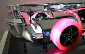
For interest, I will also mention what considerations were given to the modular design concept in the automotive industry in the early nineties of the last century. For example, Mercedes-Benz engineers at that time were working on the VRC concept – Vario Concept Car – Figure 14. The result was a fully functional vehicle prototype that combined a convertible, coupe, station wagon, and pick-up. A good option for different uses for one car. In terms of design, it is nothing spectacular, but the variability of the vehicle was exemplary. Unfortunately, after its introduction in 1994, this concept ended up in a museum, and Mercedes, just like other car manufacturers (e.g., Lancia, Chrysler, Citroen, Nissan, Fiat and also Škoda with the prototype of the Felicia FUN model, where a two-seater pick-up could be turned into a beach vehicle for four by sliding the rear wall), which were preparing similar modular concepts, continued to produce only single-purpose cars.
 |
| Figure 14: Modular automotive design concept – four-in-one – Mercedes-Benz VRC |
As runs through the entire article – in car manufacturing, the use of plastics can not only replace traditional metal materials but also effectively reduce vehicle weight. Let us use the example of an exterior part, the Outside mirror cover – Figure 15 – to explain why this is the case.
 |
| Figure 15: Exterior injection molding – Outside mirror cover |
Car outside mirror covers can be classified as exterior and aesthetic parts. They are usually injection molded from ABS, PC/ABS, ASA, PBT + GF, PC, etc. As a representative of a polymer material for the injection molding of the Outside mirror cover, we will choose ABS granulate.
The choice of ABS (amorphous copolymer acrylonitrile-butadiene-styrene, density 1.045 g.cm-3) or related polymer materials is based on the compatibility (mutual consistency) of its complex properties with the requirements imposed by the automotive industry on this type of parts:
- good mechanical properties – impact resistance – the butadiene component of ABS gives the material high toughness that withstands the impact of flying debris during car operation, during its maintenance – washing, parking, including minor collisions during operation, which reduces the risk of breaking the cover; stiffness – acrylonitrile and styrene provide sufficient structural strength to ensure a low degree of deformability during long-term use under various external conditions
- simple processability – suitability for injection molding technology – the ABS material portfolio offers a choice of the necessary flowability in relation to the design of the given cover; it is suitable for efficient injection molding of complex geometries; it also allows the production of fine shapes on mirror covers; its properties are friendly to surface appearance finishes – gloss, patterns, textures, painting, metallizing – it is suitable for various aesthetic solutions to the requirements of different car models
- price, weight – compared to the aforementioned thermoplastics used for the production of Outside mirror cover moldings, ABS is the most cost-effective – the average price per kilogram of ABS is approx. 2.21 EUR, the same price for PC is 3.22 EUR; the density of the materials, which determines their weight, is also favorable – ABS 1.045 g.cm-3, ASA 1.07 g.cm-3, PC/ABS 1.15 g.cm-3, PC 1.21 g.cm-3
- resistance to environmental influences – temperature resistance according to the requirements of the automotive industry -20 °C to +80 °C is met (maximum permanent temperature resistance approx. 105 °C); possibility of additive treatment against UV radiation and other natural conditions, choice of materials that have listed in their data sheets, for example: High Weatherability or Weatherseal applications
- safety requirements and regulations – possibility of selecting granulates with UL 94 V-0 flame retardancy, complying with the safety requirements of individual car manufacturers – materials are usually listed in the specific approved material list of the given car manufacturer; chemical resistance – data from the granulate manufacturer regarding the chemical stability of the material
- maintenance and sustainability – easy replaceability with an original spare part in case of failure; recyclability – preferably mechanical recycling, possibility of returning the material to the circulation
CONCLUSION
In conclusion, I will provide a few examples demonstrating, despite problems with end-of-life solutions for thermoplastic injection moldings, their advantages both in terms of weight savings compared to traditional metal materials and in terms of the weight-to-mechanical-properties ratio. The density, tensile strength, and modulus of elasticity themselves are far lower for plastics than for metal materials, which at first glance puts them at a disadvantage for use as structural materials. This differs from specific tensile strength, which, in addition to the tensile strength itself, also takes into account the density of the specific material. In our case, specific tensile strength is defined by the ratio of tensile strength Rm and the density of the given material. When determining the specific tensile strength, aluminum was used as the reference standard – its dimensionless value was set as 1. The other tensile strength values are therefore divided by the strength of aluminum, and thus we obtain proportional values that show how the dimensionless specific tensile strength of a given polymer differs compared to the specific tensile strength of aluminum.
A comparison of the density of some polymeric materials in relation to the density of metal materials is shown in the following images – Figure 18, 22, as well as a comparison of tensile strength Rm – Figure 19, 23 and specific tensile strength Rms – Figure 16, 17, 20, 21, 24, 25.
 |
| Figure 16: Comparison of specific tensile strength of polyolefins – PE, PP – with metal materials |
 |
| Figure 17: Comparison of specific tensile strength of unfilled amorphous polymer materials with metal materials |
 |
| Figure 18: Comparison of density of selected structural composite materials with polymer matrix – SV 30 – and unfilled polymer materials – POM, PVC (PAK = polyester alkyd = thermoset) – with metal materials |
 |
| Figure 19: Comparison of tensile strength of selected structural composite materials with polymer matrix – SV 30 – and unfilled polymer materials – POM, PVC (PAK = polyester alkyd = thermoset) – with metal materials |
 |
| Figure 20: Comparison of specific tensile strength of selected composite materials with semi-crystalline polymer matrix with fibrous filler – SV 30 – and unfilled semi-crystalline polymer materials – POM (PAK = polyester alkyd = thermoset) – with metal materials |
 |
| Figure 21: Comparison of specific tensile strength of composite materials with amorphous polymer matrix and fibrous filler – SV 30 – and unfilled amorphous rigid PVC with metal materials |
 |
| Figure 22: Comparison of density of high-tech polymer materials – unfilled semi-crystalline materials PI, PTFE, PEEK; composite with semi-crystalline matrix PEI SV 30; composites with amorphous matrix PPS, PSU – SV 30 – with metal materials |
 |
| Figure 23: Comparison of tensile strength of high-tech polymer materials – unfilled semi-crystalline materials PI, PTFE, PEEK; composite with semi-crystalline matrix PEI SV 30; composites with amorphous matrix PPS, PSU – SV 30 – with metal materials |
 |
| Figure 24: Comparison of specific tensile strength of high-tech polymer unfilled semi-crystalline materials – PI, PTFE, PEEK – and composite with semi-crystalline matrix and glass fiber PEI SV 30 – with metal materials |
 |
| Figure 25: Comparison of specific tensile strength of high-tech polymer composite materials with amorphous matrix and 30% SV with metal materials |
End of the last part.
The first part can be found here.
The second part can be found here.
The third part can be found here.
-

Jiří Češka, Nástrojárna Příbram
Production of injection molds, cutting and stamping tools, CNC machining, electric discharge machining, laser welding.
Suppliers on this topic
-

Docter Optics s.r.o.
Optical components and systems, optical lenses, PMMA lenses, plastic injection molding, glass molding, surface… -
Plasted spol.s r.o.
Plastic processing, production of plastic products, production of plastic windows, plastic window profiles, plastic… -

Tecmaplast CZ, s.r.o.
Plastic molding plant, plastic injection plant, plastic production for the automotive industry, technical plastic…Kněžnice 125
Jičín
-

KOH-I-NOOR MACHINERY a.s.
Development and production of tools, injection molds, blow molds, plastic injection, blow molding machines for… -

Mateja Plasty, s.r.o.
Processing of thermoplastics and thermosetting plastics using injection molding, extrusion and blow molding. -

SUNAP plastové součásti s.r.o.
Plastic components, plastic caps, protective caps, plastic plugs, plastic plugs, plastic caps, lids, caps, plastic…



ALLROUNDER e TREND: ARBURG Sets a new standard in electric injection moulding machines
21.9.2026 Rising energy costs, pressure to improve production efficiency and a shortage of skilled workers are changing how plastics processors assess new investments. ARBURG is responding to these trends with the launch of its new ALLROUNDER e TREND series...


Most read in the last 7 days
-
Polymer prices - polyolefin price increase without panic buying
-
CHI MEI – ABS Polylac® - the next generation from Biesterfeld Interowa GmbH&Co KG
-
Composites with thermoplastic matrix and automotive, Part 3
-
WITTMANN BATTENFELD at the Compamed presented Micro Injection Molding with LSR
-
On the same wavelength: Visit K.D. Feddersen at Fakuma 2026




Most read in the last 7 days
-
Polymer prices - polyolefin price increase without panic buying
-
CHI MEI – ABS Polylac® - the next generation from Biesterfeld Interowa GmbH&Co KG
-
Composites with thermoplastic matrix and automotive, Part 3
-
WITTMANN BATTENFELD at the Compamed presented Micro Injection Molding with LSR
-
On the same wavelength: Visit K.D. Feddersen at Fakuma 2026