


Lubomír Zeman: Plastic injection molding and surface quality, part 3
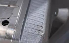
Surface Finishing – Polishing, Chipless Methods, Texturing
After machining processes, traces of the machining tool or process usually remain on the surface of the mould's cavity-forming component. During moulding, these traces are transferred as a negative impression onto the surface of the moulded part, which is detrimental to demoulding and often also to its appearance. Mould cavity-forming components are therefore finished according to customer requirements for surfaces: without additional finishing, with polished surfaces or with textured surfaces – creating structures on the surfaces of cavity-forming components.
Textures and glossy or matt surfaces on thermoplastic moulded parts are usually produced by replicating the surface structure of the injection mould's cavity-forming components. Depending on the specific requirement, a wide range of technologies can be used to create a textured mould surface – polishing, electrical discharge machining, photochemical etching, laser engraving, sandblasting, engraving, etc.
The draft angles of the moulded part walls must be adapted to the type and depth of the texture, with an allowance for releasing the texture added to the demoulding draft angle. The recommendation is to increase the demoulding draft angle by 1° for every 0,015 mm to 0,020 mm of texture depth. The texture introduces a depth that is not accounted for in standardised dimensional tolerances and geometrical deviations, and the depth of textures, for example laser-generated textures, can be of the order of tenths of a millimetre or more.
Polishing
Polishing is usually the final operation after machining and fitting the cavity-forming components of injection moulds. It removes minor irregularities and achieves the required surface quality – a technical or mirror finish, with a machined surface quality of up to Ra < 0,1 μm. Unlike grinding, it involves only a small amount of material removal, eliminating only the peaks of irregularities left by previous machining. Three basic polishing methods are distinguished:
- mechanical polishing – the most commonly used method in mould manufacturing, performed manually or by machine. Its principle is the mechanical removal of material from the part being polished through the action of hard abrasive grains, which are either firmly attached to the polishing tool or applied loosely between the tool and the part being machined and polished
- chemical polishing – this method is based on material removal through the chemical action of a suitable solution on the surface of the part. A chemical reaction occurs, removing material from the peaks of surface irregularities
- electrochemical polishing – material is removed by electrochemical dissolution of the peaks of surface irregularities. The component being polished acts as an anode immersed in a suitable electrolyte between cathodes positioned appropriately for the shape of the workpiece
Technical polishing is performed, for example, to prepare a surface for photochemical texturing, laser texturing, painting or coating, or as a final surface finish to facilitate removal of the moulded part from the mould cavity. Polishing preserves the dimensional and geometrical accuracy of the part. Metal materials as well as aluminium alloys, cast irons, and copper or graphite electrodes are polished.
A certain difficulty arises when describing the quality of the finish in words – technical, high-gloss and mirror finish:
- technical finish – removal of machining marks from cutting or electrical discharge machining – used primarily for polishing cavity-forming surfaces in the direction in which moulded parts are removed from the mould, Ra approximately 0,8 μm
- high-gloss finish – visible areas of moulded parts, or ribs that are problematic in terms of removing the moulded parts from the mould, Ra approximately 0,4 μm
- mirror finish – where surfaces with demanding appearance requirements and optical moulded parts are required, Ra approximately 0,04 μm
Sometimes polishing quality is specified by abrasive grit size, for example:
- polishing for subsequent texturing of moulded part surfaces – grit size 220 to 400, Ra 0,51 μm to 0,32 μm
- polishing for subsequent painting of moulded part surfaces – grit size 400, Ra 0,32 μm
- polishing for subsequent chrome plating of moulded part surfaces – grit size 800, Ra 0,14 μm
Polishing of mould cavity-forming components is most often performed manually, using various polishing materials and handheld polishing machines. The type of finish must always be specified before polishing – a technically polished component can be further processed to produce a high-gloss finish, but mirror polishing requires a polishing process appropriate to the required finish. If the component has already been technically polished, its surface must be roughened before mirror polishing can begin; this is usually carried out by staff from specialist polishing companies.
Abrasive Papers
Abrasive paper, emery paper, sandpaper – different names for the same aid, which, thanks to its properties and construction, can effectively remove material or dirt, or accumulated surface layers, prepare surfaces for further processing or create high-quality surfaces.
The question – what is abrasive paper – has a fairly simple answer: abrasive grains are bonded to a backing, most commonly thin cardboard or a synthetic (synthetic – produced by industrial synthesis, as opposed to substances formed naturally in living organisms through biosynthesis; created, manufactured by humans, as opposed to being of natural origin) nonwoven fabric or cotton cloth, using a binder – various types of synthetic resins – and are coated with an antistatic layer to prevent dust particles from adhering.
The abrasive grain material determines the suitability of emery paper for a particular type of work and the material being worked on. Abrasive grains are most commonly made of:
- corundum (aluminium oxide Al2O3), which is suitable for sanding wood, plastics, metals and other materials
- silicon carbide (silicon carbide SiC, carborundum), suitable for working on hard materials such as metals, ceramics or glass
- silicone carbide (quartz), suitable for sanding wood, plastics and metals
- almandine (garnet), intended for sanding metals, wood or plastics
- ceramics for grinding metals (they leave a coarser surface)
- diamond for grinding the hardest materials
- cubic boron nitride (CBN) for grinding hardened materials or tool steel
The determining parameter for achieving the desired results is grit size – grit, the grade of abrasive paper (grit size – grit is a term used for all abrasive products). According to the Federation of European Producers of Abrasives – ISO / FEPA, Federation of European Producer of Abrasives – abrasive grit size is a number indicating the number of sieve openings per inch (1“ = 25,4 mm) through which the abrasive passes during sieving. The letter P and the term “GRIT” are usually added to this numerical designation. The higher the grit designation, the finer the sanding, and conversely, the lower the grit number, the coarser the abrasive paper:
- P12 – P100 – these papers have large grains and are used to remove thick layers of material and shape worn surfaces
- P100 – P180 – ideal for removing various contaminants and working on surfaces that have already been shaped
- P200 – P800 – medium-grade paper is suitable for smoothing surfaces, matting and correcting paintwork or preparing material before painting
- P1000 – P2500 – used exclusively for sanding to a gloss, cosmetic changes or touch-ups
In words, emery paper grit sizes are designated according to FEPA as:
- coarse (grit sizes 7, 8, 10, 12, 14, 16, 20, 22, 24, 30) – example: Grit P 12 = average grain size is 1 815 µm = 1,815 mm
- medium (grit sizes 36, 40, 46, 54, 60)
- fine (grit sizes 70, 80, 90, 100, 120)
- very fine (grit sizes 150, 180, 220, 240)
- particularly fine (grit sizes 280, 320, 400, 500, 600)
- extra fine (800, 1000, 1200, 2500) - example: Grit P 2500 = average grain size is 8,4 µm = 0,0084 mm
Other standards used to specify grit size are the American ANSI – American National Standards Institute – with numerical designations from 12 to 1000, and the Japanese JIS – Japanese Industrial Standards Committee. FEPA marking is identical to the standard ISO 6344-1,2,3:1998 – Part 1 Grain size distribution test ; Part 2 Abrasives - grain size analysis - Determination of the grit size distribution of macrogrits – macrograins P12 to P220 – Part 3 Abrasives - grain size analysis – Determination of the grit size distribution of macrogrits – macrograins P240 to P2500.
Alongside grit size, abrasive density also plays an important role, meaning how densely the abrasive grains are applied to the paper:
- if the entire surface of the paper is covered with grains, it is a closed coat, which is suitable for working on metals
- if 70 – 80 % of the paper is covered with abrasive grains, it is a semi-open coat suitable for sanding hardwood
- with only 50 % coverage, it is referred to as an open coat, and such abrasive paper is suitable for sanding resin-rich softwoods or removing old coatings
Whether the abrasive paper will be used dry or wet also plays an important role. For wet sanding, it is advisable to choose a slightly higher grit rating than for dry sanding, bearing in mind that before wet sanding you must soak the abrasive paper in water for several minutes. And let us not forget that abrasive papers intended for wet sanding are not suitable for dry sanding.
In Europe, diamond abrasives are designated by grit size according to the standard
ISO 6106:2013 Abrasive products — Checking the grain size of superabrasives; Abrasive products – Checking the grain size of superabrasives. The standard specifies the mean diameter of the diamond crystal in micrometres, and the numerical designation is preceded by the letter D – an example is given in Table 5. As we can see from the table, the designation of diamond abrasives is the reverse of that used for abrasive papers – the higher the number in the designation, the coarser the grain.
| Table 5 : Diamond abrasives – designation and mean diamond crystal size |
Photochemical texturing
The essence of photochemical machining, the creation of textured surfaces, lies in the controlled etching away of material from the mould-forming component to a depth ranging from a few hundredths of a millimetre to a few tenths of a millimetre (up to approx. 0.2 mm). The principle is a chemical reaction between the workpiece material and the reactive environment of the bath in which the workpiece is immersed. Special coatings – masks – are applied to areas that must remain unaffected during the etching process, protecting the workpiece material from the action of the reactive environment of the etching bath, thereby creating raised and recessed areas on the surface of the mould-forming component – the texture.
Photochemical texturing involves the following procedure:
- definition of the texture or its creation, generation (creation according to specific rules) – specialist companies providing custom photochemical texturing services have texture sample books; individual car manufacturers, which most commonly use these textures on their plastic interior parts, have their own approved texture types; new types are developed in cooperation with texturing companies
- a photographic negative at a scale of 1 : 1 is produced from the texture definition
- the component to be textured is thoroughly cleaned, the surface to be textured has been technically polished, and a photosensitive substance – photoresist – is applied to it as a protective mask, a light-sensitive layer resistant to the environment of the etching bath
- the photographic negative containing the texture definition is placed on the photoresist and exposed to ultraviolet radiation, hardening the mask in the required areas, and the unhardened coating is removed from the surface
- in the reaction bath, the unprotected areas are etched away at a rate of approx. 0.01 mm/min. to 0.05 mm/min.
- after controlled etching, the mask is removed from the component, which is then cleaned, and the texture is inspected
- because a great many different and varied shapes are textured, the work is predominantly manual and requires a certain amount of time
The described photochemical texturing process also entails a certain limitation of this texturing technology – ribs on injection-moulded parts located on their visible surfaces are very difficult to texture photochemically, or cannot be textured with any guarantee. With this type of visible surface design, the feasibility of texturing must always be discussed with the relevant texturing facility.
A selection from the photochemical texture sample book of Mold-Tech Standex Bohemia, Liberec is shown in Figure 21. Figure 22 illustrates the sequence of a similar technological process for creating a texture – chemical etching. In both processes, the required gloss is achieved by sandblasting.
| Figure 21 : Examples of photochemically etched textures |
| Figure 22 : Principle of chemically creating textures on the surface of injection mould forming components |
Electrical discharge texturing
The term electrical discharge machining (EDM – Electro Discharge Machining) encompasses several specific methods whose common physical principle is material removal by melting and vaporisation using repeated electrical or arc discharges. No chips are produced, unlike conventional machining with cutting tools; it is a process that uses no cutting forces.
A prerequisite for electrical discharge machining is that the workpiece must be made of an electrically conductive material. Machining operates on the principle of two electrodes, one of which is the workpiece (anode) and the other the tool (cathode). Both electrodes are immersed in a dielectric fluid (a fluid with high electrical resistance, such as machine or transformer oil, kerosene, various salt solutions and others) and are separated by a spark gap. A diagram of electrical discharge machining is shown in Figure 23.
| Figure 23 : Diagram of electrical discharge machining , set of Cu electrodes ,electrical discharge machining |
The material removal process is based on pulsed discharges distributed over the entire active surface of the tool electrode. Each discharge erodes the material and creates a small crater on both the workpiece and the tool. Microparticles melted and vaporised from both the tool electrode and the workpiece during the process are flushed away from the discharge erosion site by the flowing dielectric. In some processes, the tool electrode may oscillate, improving dielectric flow and flushing the resulting microparticles out of the spark gap.
The temperature at which the material vaporises varies depending on whether an electric arc (a temperature of 3 600 °C to 4 000 °C for 0,1 ms to 0,1 s) or a spark discharge (a temperature of up to 10 000 °C for 0,01 ms to 0,1 ms) is used. Figure 24 shows the relationship between roughness and discharge duration.
| Figure 24 : Relationship between surface roughness and discharge duration |
Die-sinking EDM is the basic method of EDM machining. During die sinking, the electrode advances towards the workpiece while maintaining a constant distance between the workpiece surface and the tool electrode; the spark gap ranges from 0,01 mm to 0,50 mm. The working surface of the tool electrode is formed as the negative of the desired surface of the machined part; discharges and the advancement of the electrode into the workpiece reproduce its shape in the workpiece.
EDM texturing is a finishing operation performed using the same principle and manufacturing process as die sinking, with the aim of creating a texture on the machined surface.
Electrical or arc discharges between the tool electrode and the machined surface create craters on that surface which, when a suitably machined electrode is used, can have a specific depth and structure. This makes it possible to create a defined roughness – a texture – on the surface of the moulded part.
The definition of a texture created by electrical discharge machining is based on the German standard VDI 3400 Electrical Discharge maschining: Definitions, Process, Applicaton from 1975 (VDI = Verein Deutscher Ingenieure, Association of German Engeeners, Association of German Engineers). This standard defines 46 roughness grades from grade 00 (Ra 0,1 µm) to grade 45 (Ra 18 µm).
To ensure the universal use of EDM textures, a sample chart was created – VDI 3400 Ref. XX – where XX is the number of the specific VDI texture according to the sample chart. The EDM texture reference standard contains textures from the VDI 3400 scale, namely: 12,15,18,21,24,27,30,33,36,39,42,45; it covers roughness from Ra 0,4 µm to 18 µm – Table 6 and Figure 25.
| Table 6: VDI 3400 Ref. xx – comparison of the EDM texture number with the surface roughness value Ra |
| Figure 25: EDM texture sample charts according to VDI 3400 Ref. xx |
Conversion tables or graphs defining the relationships between individual roughness values measured and calculated using different methods can be found in the technical literature. A table is also available that converts roughness values according to the sample chart of the Swiss EDM machine manufacturer Charmilles into Ra values – see the tables and graph in Figure 26.
| Figure 26: Graph and tables for roughness conversion : 1 – upper limit for Rz ; 2 – upper limit for Ra |
Laser Texturing
One of the advantages of laser technologies in general is that they are suitable for surface treatment by engraving (removing material from the surface) and marking, for virtually all materials – all metallic materials, including surface-treated parts, non-ferrous metals, plastics, graphite, glass, wood, leather, ceramics, paper, rubber, silicone, minerals, etc.
Laser technologies are used to create an indelible graphic or other motif on the working surface. The motif is created by the thermal action of a laser beam, which removes a layer of material of a certain thickness from the surface (the workpiece material is vaporised), or the surface is hardened, creating a visual effect; changes to the beam parameters allow the quality of the marking, texture, etc. to be varied. The advantage is that the process is non-contact and does not affect the surrounding material, except at the point where the focused laser beam (focused on the given location) strikes. In addition to marking, various reliefs and textures can also be created, with depths of up to several millimetres.
Depending on the complexity of the texture motif, a distinction is made between 2D engraving, where the bottom of the engraving on the machined part is at a single constant depth, and 2.5D engraving, where a multilevel motif can be created. This technology also allows control over details of the required motif such as its roughness. Samples of laser-machined surfaces are shown in Figure 27.
| Figure 27: Examples of surfaces – textures created using laser technology |
One disadvantage of creating laser-engraved textures is the need for a computer-based definition of the texture to control the machining laser, and the time required to create the texture, which depends on its complexity and depth – the texture is formed by vaporising the mould cavity material point by point. Since the base material is vaporised by a laser beam, which carries the machining energy, geometric limitations must be taken into account – the laser beam cannot reach the surfaces of deep or otherwise obscured features.
Chipless Finishing Methods
Chipless finishing methods are now more or less declining in importance and are being replaced by other methods of creating surfaces.
Chipless methods involve plastic deformation of the surface layer of the workpiece and, in the manufacture of cavity-forming components of injection moulds, aim to improve the surface quality of the components and create their structure – a textured surface. Plastic deformation extends to a depth of a few millimetres. As a result, the surface texture parameters improve and its strength and hardness increase. Favourable residual stresses develop in the surface layer, and the fatigue limit and resistance to wear and corrosion increase.
The most commonly used chipless surface treatment method is abrasive blasting – propelling abrasive particles against the surface of the part. Other chipless methods include shot peening (propelling metal or ceramic beads against the surface of a cavity-forming mould component) and glass bead blasting (propelling glass microbeads). The same group also includes roller burnishing (treating the workpiece surface with a rotating shape – a ball, roller or barrel – under rolling friction) and diamond burnishing (treating the surface with a fixed diamond tip under sliding friction).
As already mentioned, abrasive blasting, shot peening and glass bead blasting are methods based on the principle of propelling active particles – abrasive grains of various shapes and sizes and made from various materials (organic and mineral), metal and cast-iron shot (diameter 0.3 mm to 3 mm), and glass and ceramic beads (diameter 0.03 mm to 0.8 mm) – against the surface of the component being treated using a jet of compressed air (most commonly) or liquid. Active particles made from mineral materials, metal or cast iron leave abrasion marks on the treated surface.
The surface roughness achieved ranges from Ra 0.8 μm to 1.6 μm. Abrasive particles can strike the surface at speeds of up to 150 m.s-1.
Blasting technologies are used to texture the surfaces of cavity-forming mould components, to clean them where necessary, and to adjust the gloss of surfaces textured by other methods, for example photochemically.
Abrasive blasting is usually carried out manually in blasting cabinets; areas that are not to be blasted must be protected and masked. The disadvantage of manual blasting is that surface quality depends on the human factor.
Cleaning, Degreasing and Corrosion Protection of Mould Surfaces – Cavity-Forming Components with Machined, Glossy or Textured Surfaces
I have already mentioned in the preceding text that, before applying technologies that establish surface quality, these surfaces must be clean and, in some cases, also degreased. Following surface treatment, the surfaces of injection mould cavities are polished, textured or treated to facilitate ejection of the moulding from the mould. The surfaces often become fouled with by-products released from the plastics being injection moulded and other contaminants, such as lubricant residues, residues of degraded material, etc. These processes result in a non-conforming moulding and the possibility of its delivery to the customer, or a complaint concerning the mouldings or the entire batch supplied.
Incomplete removal of residues and contaminants also allows corrosion to develop, even beneath the protective preservative film. Corrosion can also develop if a corrosion protection product is applied to a damp mould surface.
If degreasing is complete, there is a risk of corrosion of the mould surfaces due to atmospheric moisture. It is therefore always necessary to apply corrosion protection to the mould surfaces as soon as possible.
Methods of removing contaminants: mechanical; solvent-based; dry ice blasting; ultrasonic; laser; thermal.
For degreasing, particularly glossy surfaces, it is necessary to use fast-evaporating degreasing agents that do not leave patchy marks on the surface (foreign impurities in the solvents).
After glossy, matt, textured and other surfaces have been produced, these surfaces have no corrosion protection. In corrosion protection practice, the most important requirements are reliable preservation, penetration into narrow gaps and resistance to running off vertical surfaces.
Preservatives, usually in spray form, which makes it very easy to cover the entire protected area with a dry, solid film, are applied to cleaned and dry mould surfaces. Some products also allow visual inspection of the application of the preservative film, as they are coloured.
It is advantageous to use corrosion protection products that do not need to be removed after the mould has been installed on the injection moulding machine. During injection moulding, these products act as release agents and are removed from the mould cavity surfaces after a few cycles.
Selected errors and shortcomings when using cleaning agents, degreasers, lubricants, preservatives and release agents:
- use only products whose intended purpose matches the purpose of the injection mould maintenance
- when lubricating – sprays, liquids, pastes, dry-film coatings – observe the following rules: lubricate according to the lubrication schedule, apply a thin film to a dry substrate over the entire surface – note: this is not bread spread with lard
- mechanical cleaning – all cleaning materials must be softer than the material of the mould components being cleaned and non-abrasive
- preservatives must not be applied to wet surfaces
- some corrosion protection products contain water and are therefore unsuitable for mould preservation
- new products must always be tested for the intended application – for example, some fast-evaporating agents may leave patchy marks on the cavity surface
- after degreasing the mould surfaces and contours, atmospheric moisture may cause corrosion of the surfaces and contours
- incomplete removal of residual contaminants and fouling allows corrosion to develop even beneath the protective preservative film
- the products used must always have an operating temperature higher than the mould temperature
End of Part Three. To be continued: 16. 1. 2026
You can find Part One here.
You can find Part Two here.
Cover photo: R & D MOLD MACHINING s. r. o.
-

Jiří Češka, Nástrojárna Příbram
Production of injection molds, cutting and stamping tools, CNC machining, electric discharge machining, laser welding.

Suppliers on this topic
-

FORM s.r.o.
Glass-reinforced plastics, fiberglass, thermoplastic products, painting of plastic products, metal production and… -

LPH GROUP
Technical and aesthetic moldings made of thermoplastics, production of injection molds for thermoplastics, surface… -

Docter Optics s.r.o.
Optical components and systems, optical lenses, PMMA lenses, plastic injection molding, glass molding, surface… -

KOH-I-NOOR MACHINERY a.s.
Development and production of tools, injection molds, blow molds, plastic injection, blow molding machines for… -

DIXI, výroba plastových obalů a.s.
Plastic bottles, plastic canisters, plastic packaging, closures, blow molds to order, CNC machining, chip machining. -

3M TRADE - PLASTIC PARTS s. r. o
Plastic molding, plastic injection, injection molds, molds, industrial robots, manipulators, grippers, EOAT components.


DESMA Open House 2026: Innovation, Practical Application, and International Exchange
28.10.2026 Under the motto “Built right. Runs right.”, DESMA opened the doors of its main plant in Fridingen on October 1, 2026, and welcomed over 280 visitors from around the world to a thoroughly successful Open House.


Most read in the last 7 days
-
Polymer prices - october price increases partly successful, with minor corrections expected in the week ahead
-
Polymer prices - Year-End Polymer Price Scenarios
-
Long-lasting solution: Radiation-crosslinked PE-Xc pipes for drinking water supply
-
Polymer prices – the increase in olefin monomer contract prices in October was in line with expectations
-
Plastica-expo 26





Most read in the last 7 days
-
Polymer prices - october price increases partly successful, with minor corrections expected in the week ahead
-
Polymer prices - Year-End Polymer Price Scenarios
-
Long-lasting solution: Radiation-crosslinked PE-Xc pipes for drinking water supply
-
Polymer prices – the increase in olefin monomer contract prices in October was in line with expectations
-
Plastica-expo 26