


Lubomír Zeman: Plastic injection molding and surface quality, part 1
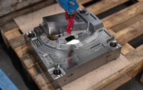
INTRODUCTION – Surface Quality in Thermoplastic Injection Moulding – Roughness of Injection Mould Cavity Components x Gloss, Matt Finish or Texture of the Shapes and Surfaces of Thermoplastic Mouldings
In engineering and plastics processing practice, a complete description of tolerancing in technical documentation is an unambiguous tool for meeting the requirements of the moulding designer, who has incorporated all the required functional properties into its design. As a result, the final product is not influenced by the personal opinions of individual workers, and conforming parts are clearly distinguished from rejects during quality control. The outcome depends on the optimal specification of tolerances, compliance with them during production and subsequent correctly performed product inspection.
The quality characteristics being inspected, usually functional properties, must be accompanied by their tolerances (reproducible production of parts with zero tolerance is not feasible in manufacturing practice), which can be divided into two main groups – material property tolerances and geometrical tolerances. Geometrical tolerances are divided into several subgroups: dimensional tolerances, form tolerances, position tolerances and roughness tolerances.
Roughness is a property that forms part of the surface and, together with other parameters, is included in the concept of surface integrity. The surface integrity of an injection mould cavity is a combination of properties listed in Figure 1.
| Figure 1: Surface integrity of an injection mould cavity |
Surface integrity describes the interrelationship between the geometrical (particularly dimensional) and physical (particularly material) properties of a surface, with the individual properties determining the service life and the ability of the surface to perform the required functions.
Material tolerances describe uncertainties in the chemical composition of a material, its structure at the atomic level and its physical properties. Physical properties include, for example: elasticity, strength, hardness, magnetic properties, thermal and electrical conductivity. These properties of the base material may differ from those in the surface layer, which will be our further focus from a functional perspective.
We consider surface integrity to be the relationship between the required functional properties of a surface and the change in the properties of the new surface created by manufacturing using a particular technological process. This is caused by the relationship of micro-irregularities (geometrical properties) to physical properties (stress and hardness). A surface can be evaluated using two basic surface characteristics, namely the spatial arrangement of the surface and the physicochemical properties of the surface layer.
One of the most important parameters influencing surface quality, the operating properties of the surface, and the reliability and service life of a product – a mould cavity component – is its surface quality.
Surface quality is a set of properties of the examined surface of a given object, which we divide into properties of the spatial arrangement of the surface – roughness (texture – surface structure, morphology – the study of shapes) and physical and chemical properties. In general, properties such as efficiency, reliability, functional properties, external appearance and, last but not least, costs relating to the entire manufacturing process depend on surface quality. In machining, we influence surface quality by selecting the workpiece material, the correct cutting tool, suitable cutting conditions, the coolant, etc. For dynamically loaded components, we consider fatigue factors and the properties of the selected material, and examine fatigue fracture, which originates on the surface of the component or immediately beneath it. In terms of static loading, we most commonly encounter cases of compressive, tensile, bending and torsional loading, where the highest stress again occurs on the surface of the component. Resistance to corrosion under operating stress must be considered in relation to surface microgeometry and the subsequent risk of fatigue fracture.
Quality is information about a property of something and answers the question “what kind?” – in Latin, qualis? – just as the concept of quantity (amount) answers the question “how much?” – in Latin, quantum?. Quality is usually directly accessible to our sensory perception (the judgement and abilities of the observer), unlike quantity, which must be determined by measurement (counting, weighing, etc.). However, this does not mean that, when evaluating quality, we are unable, as with quantity, to objectively verify these indicators on the basis of defined indicators.
The standard STN EN ISO 9000:2015 Quality management systems - Fundamentals and vocabulary. The standard describes the principles of quality management systems and specifies the terminology of quality management systems. The standard defines quality as follows:
Quality – the ability of a set of inherent (intrinsically linked, inseparable) characteristics of a product, system or process to fulfil the requirements of customers and other interested parties.
The definition of quality implies that it is a relative concept (assessed in relation to something) and can only be expressed when related to a specific customer or market segment. The same type of product can serve different purposes, and customer segments may have different requirements for the product.
ČSN EN ISO 8785:2000 Geometrical product specifications (GPS) - Surface imperfections – Terms, definitions and parameters. The standard defines terms for surface imperfections for use in technical documents, technical drawings, scientific publications, etc. It specifies the extent to which surface imperfections are permissible and assists in determining methods for measuring them.
Surface texture requirements are an essential part of the specification of engineering products (for example, injection moulds) and, by extension, plastic injection-moulded parts. Surface texture – surface texture - is defined in the above-mentioned standard ČSN 8785 as a set of repeated or random deviations from the geometrical surface that form the three-dimensional topography (description of surface shapes) of that surface.
Surface texture is most commonly assessed using contact profilometers (2D measurement). Recently, 2D measurement has been supplemented by measurements using non-contact optical or laser devices (3D measurement), which are capable of measuring and subsequently evaluating a considerable number of parameters, whether the aforementioned profile parameters (2D) or areal and volume parameters (3D). This has significantly expanded the range of options for assessing surface texture. Surface texture, i.e. its arrangement and shapes in terms of macro- and microgeometry, is an important element that determines significant properties of components – see above. Surface texture includes roughness, waviness and form deviation of the surface under examination. The differences between these texture characteristics are determined by the ratio of the spacing of irregularities to their height. For roughness, this ratio is 1:50; for waviness, it is 50:1 000; for surface form deviation, the value is above 1 000. From a geometrical perspective, the size, shape and relative distribution of surface irregularities in machining are determined by the shape of the cutting tool edge and the conditions that determine the trajectories of the tool edge relative to the machined surface. Surface structure, comprising the aforementioned roughness, waviness and basic surface profile, has a decisive influence on the properties and behaviour of components in service (for example, on the progression of wear, fatigue properties, joint strength, kinematic and dynamic interactions between surfaces, etc.). Surface structure, together with the properties of the surface layer, is decisive for the service life and functional reliability of components.
From an engineering and plastics processing perspective, the concepts of texture and surface roughness are primarily associated with the surface quality of machined injection mould components. In plastics injection moulding, when considering moulded parts and their surfaces, we usually work with the terms – gloss, grain.
Gloss is a physical quantity that assesses the ability of the surface of an object made from a given material to reflect light under certain geometrical conditions with different directional reflection properties. Gloss is the visual impression we have when assessing a product with our eyes. The more light is reflected from the surface, the glossier the surface will appear to us. Smooth and highly polished surfaces are visibly glossier, while uneven, roughened surfaces are more matt. Naturally, the lighting under which we visually assess gloss and the angle at which we view the surface are important. Since each of us has different eyes and an individual's assessment of gloss cannot be considered objective, instruments must be used to measure gloss objectively and accurately. By measuring gloss, we determine not only a basic parameter such as surface glossiness, but can also use the gloss level, for example, to identify deviations in the effect of injection moulding process parameters on the appearance characteristics of moulded parts that have occurred as a result of using a different process or material. A gloss deviation identified in this way may be associated, for example, with the loss of other surface properties of the material – poor replication of the surface of the mould cavity components – their transfer to the surface of the moulded part.
The concept of “smoothness” or “roughness” in gloss assessment and in machining is completely different – roughness is a succession of small surface irregularities in materials resulting from machining. The term “surface roughness” does not include grain on the surface, polishing or surface defects.
I have not found a usable definition in the specialist literature for the term “grain” as used in the plastics industry. In general, it can be described as an aesthetic surface finish of a moulded part, a pattern on the surface of a component, or the creation of an indelible spatial, volumetric, 3D graphic or other motif on the surface of a moulded part. Methods for creating grains are described below.
In general, two types of surfaces are most commonly distinguished on thermoplastic mouldings:
- appearance and functional surfaces, which may be polished, a term that also includes a “matt” finish, or textured
- other surfaces – non-functional structural surfaces (usually bearing machining marks from the mould cavity components), surfaces required for the manufacturability of the moulding's design (for example, local relief, ribs, etc.), and surfaces that facilitate the ejection of mouldings from the mould cavity (most commonly drafted surfaces and shapes, usually polished to a technical finish)
Surface Roughness
A surface is defined as the interface between two different environments – the base material and its surroundings. This interface determines the resulting appearance of the material in question – in our case, the surface of injection mould cavity components or mouldings. As already mentioned, the term surface quality encompasses not only the size of surface irregularities – roughness, textures – and its geometric shape, but also the chemical and physical condition of the material's surface layer.
The structure of a surface is called its texture. Texture is defined as a surface with a set of grains located between the surroundings and the surface of the moulding. The surface of a moulding is a complex system in which repeated or random deviations from the ideal geometric shape of the surface occur.
Surface roughness is defined as the portion of the geometric deviations (microgeometry) of an actual surface with small spacing between adjacent irregularities and imperfections (deviations) – peaks and valleys relative to the ideal surface profile, idealised as a smooth, glossy surface. Roughness represents a quantitative measure (numerical, with measurements that can be repeated and results compared) of the traces left by the manufacturing process that creates a new surface and of other components that constitute the surface texture, such as the material structure. A cutting tool leaves marks on the surface. The arrangement of these marks is periodic or random. The “tearing away” of material microparticles during machining, remnants of built-up edges on the cutting edge and small defects at the tool tip also produce finer components of the surface structure. Valleys and peaks are formed whenever the materials of mould cavity components are processed – machining with cutting tools, electrochemical machining, abrasive machining, forming, casting, etc. – and, as a result of the shaping of the polymer melt in the mould cavities, they are transferred as a positive replica onto the surface of the moulding.
From a technological perspective, surface roughness in the production of thermoplastic mouldings arises primarily during the manufacture of injection moulds, or their cavity components, which form the mould cavities. Primary manufacturing technologies – usually hot or cold forming – cannot create a surface with the required shape, geometric accuracy, roughness and other surface properties. The required surface is achieved only by further machining of the surface allowances on the respective semi-finished products.
The main technologies used to produce the surfaces of injection mould cavity components are chip-removal machining processes (particularly milling, drilling and grinding), in which a newly machined surface is created by the action of the cutting tool's edge on the surface being machined. The tool geometry and its kinematic action produce irregularities on the workpiece, which often exhibit a characteristic arrangement, also as a result of chemical and physical changes in the material's properties.
For many reasons, the actual irregularities differ in shape, size and frequency and have a predominant direction. These irregularities are influenced by material and technological properties. The choice of cutting conditions affects the influence of the material, since machining is caused by plastic deformation resulting from both mechanical and thermal effects. Vibration of the workpiece and tool, wear of the cutting inserts, irregularities in the tool's cutting edge, changes in the cutting environment through the supply of coolant from a nozzle or a high-pressure water jet, and friction between the tool flank and the machined surface – all these conditions are technological influences. Material factors also have a significant influence on the deterioration of surface roughness. This is primarily due to the mechanism by which the new surface is formed, which varies according to the structure and properties of the material.
Another important technology that produces surfaces with roughness or texture is electrical discharge machining (EDM – Electro Discharge Machining). Of the range of electrical discharge machining processes, die-sinking EDM, wire cutting and EDM texturing are the most commonly used. The physical process (melting, evaporation) of removing material from the relevant surface is based on pulsed electrical or arc discharges distributed over the entire active surface of the tool - the electrode. Each discharge disrupts the surface material and creates a small crater on both the workpiece and the tool. Microparticles melted and evaporated during the process, from both the tool electrode (made of copper or carbon) and the workpiece, are flushed away from the discharge site by the flowing dielectric (a substance with low electrical conductivity – an insulator – and high electrical resistance, capable of storing energy in an electric field). In some processes, the tool electrode may oscillate, improving the flow of the dielectric and the flushing of the resulting microparticles from the spark gap. The temperature at which the material evaporates varies depending on whether an electric arc is used (a temperature of 3 600 °C to 4 000 °C for 0,1 ms to 0,1 s) or a spark discharge (a temperature of up to 10 000 °C for 0,01 ms to 0,1 ms).
As I have already stated, the term surface “roughness” does not include its texture pattern, polishing or any surface defects – surface fissures, cracks, dents, scratches, etc..
Surface quality parameters – surface roughness
Surface quality consists of random or recurring deviations from an ideal surface. It is characterised by roughness, waviness – the part of the texture on which roughness is superimposed; waviness may be caused by vibration or workpiece deformation – usually due to the machine tool – low rigidity, an unbalanced grinding wheel, inaccuracies in the guideways, etc., the direction of machining marks and surface defects – see Figure 2:
| Figure 2: Surface characteristics |
The importance of surface condition in engineering practice, in our case in the manufacture of injection moulds, has been known for many years. Generally applicable rules and methodologies for describing, scanning and evaluating surfaces have therefore been developed and incorporated into the relevant standards, with widely known surface roughness parameters, most commonly Ra and Rz. In most toolmaking applications, roughness is viewed only as a profile (2D) – in a single sectional plane, along a line, which makes it impossible to capture all its properties objectively in all directions (i.e. over an area, in 3D). More comprehensive scanning methods are therefore also used – predominantly optical, or laser-based, in the form of 3D scans – areal scanning.
For illustration, I will present profile and areal roughness measurements. The profile measurement is performed at a location without a notch (Figure 3), and the second measurement across a location with a notch (Figure 4). Not only the location and direction of surface profile roughness measurement, a 2D measurement, but ultimately also the difference in the resulting roughness parameter values demonstrate the improved informative value of areal, 3D surface roughness measurements – Figures 5 and 6.
Note – for both types of measurement, the result will always depend on the choice of measurement location.
| Figure 3: Profile roughness measurement at a location “without a notch”: Ra = 333,62 nm, Rq = 437,42 nm, Rz = 2,8408 µm |
| Figure 4: Profile roughness measurement at a location “with a notch”: Ra = 1,0689 µm, Rq = 2,0907 µm, Rz = 8,2572 µm |
| Figure 5: Areal roughness – reference surface (3 x 0,5 mm) with evaluation of areal roughness parameters: Svk = 498,81 nm (average height of peaks above the roughness core), Vvv = 0,054312 ml.m-2 (void volume below the roughness core) |
| Figure 6: Areal roughness – ground surface (3 x 0,5 mm) with evaluation of areal roughness parameters: Svk = 5,44 µm, Vvv = 0,36 ml.m |
The ČSN EN ISO 4287 standard defines three geometrical profile roughness parameters: see Figure 7
- parameter P calculated from the primary profile
- parameter W calculated from the waviness profile
- parameter R calculated from the roughness profile
| Figure 7: Basic profile parameters (after filtering the measured surface profile values) |
The most commonly used parameters calculated from the roughness profile are Ra and Rz – see ČSN EN ISO 4287, Figures 8 and 9.
| Figure 8: Definition and calculation of roughness Ra – arithmetical mean deviation of the profile over the profile sampling length |
Ra – arithmetical mean deviation of the profile over the profile sampling length – is the most widely used parameter for evaluating surface quality; its disadvantage is its sensitivity to outlying values (minima, maxima). It is usually calculated using the arithmetic mean – the statistical method of determining Ra, Figure 8, formula on the left (on the right, the integral method of determining Ra) – the Ra parameter merely averages large peaks and deep valleys and provides no information about their size. Their size is indicated by the Rz parameter – the height of irregularities between the highest and lowest points of the profile – the ten-point maximum profile height.
| Figure 9: Definition and calculation of roughness Rz – the height of irregularities between the highest and lowest points of the profile – maximum profile height |
Ra and Rz values are given in micrometres (1 µm = 0,001 mm = 0,000001 m), usually in a practical series – 0,025 ; 0,05 ; 0,1 ; 0,2 ; 0,4 ; 0,8 ; 1,6 ; 3,2 ; 6,3 ; 12,5 ; 25 ; 50 µm. The recommended sampling lengths l are 0,08 ; 0,25 ; 0,8 ; 2,5 ; 8 ; 25 mm – Table 1.
| Table 1: Recommended sampling lengths depending on Ra |
The required roughness of a functional surface can be selected empirically (to a certain degree of accuracy) according to the dimensional tolerance. This is based on the fundamental assumption that surface roughness will not exceed a certain proportion of the dimensional tolerance. This can be expressed by the equation
Rz = K.TD, where Rz is the maximum profile height, TD is the dimensional tolerance and K is the coefficient given in Tables 2 and 3. The coefficient K is selected depending on the range of nominal dimensions assigned to the given tolerance and also depends on the type of fit. Recommended surface roughness values assigned to tolerance grades are given in Table 4.
| Table 2: Coefficient K depending on the fit |
| Table 3: Coefficient K according to the nominal dimension |
| Table 4: Recommended surface roughness values assigned to tolerance grades |
The standard ČSN EN ISO 25178: 2002 Geometrical product specifications (GPS) - Surface texture: Areal defines surface roughness analyses for areal (3D) measurements.
An example of the evaluation of an areal surface roughness measurement – a part manufactured using DMLS – Direct Metal Laser Sintering – or SLS (Selective Laser Sintering) – laser sintering, and a part manufactured using DMLM – Direct Metal Laser Melting – or SLM (Selective Laser Melting) – laser melting. Both are additive 3D printing technologies (layer by layer); the specimen measured 30 x 31 x 1,5 mm, DMLS – sintered layer thickness 0,04 mm, laser sintering head travel speed 100 mm.s-1.
| Figure 10: Sintered – surface of sintered powder – DMLS technology / Melted – surface of partially melted powder – DMLM technology |
| Figure 11: Detail of the scanned surface |
| Figure 12: 3D image of the evaluated surface – scanned area size 0,36 mm2 |
| Figure 13: Measurement evaluation for Ra height parameters |
| Figure 14: Measurement evaluation for Rz height parameters |
End of Part One. You can find Part Two here.
Cover photograph: R & D MOLD MACHINING s. r. o.
-

Jiří Češka, Nástrojárna Příbram
Production of injection molds, cutting and stamping tools, CNC machining, electric discharge machining, laser welding.

Suppliers on this topic
-

FORM s.r.o.
Glass-reinforced plastics, fiberglass, thermoplastic products, painting of plastic products, metal production and… -

LPH GROUP
Technical and aesthetic moldings made of thermoplastics, production of injection molds for thermoplastics, surface… -

Docter Optics s.r.o.
Optical components and systems, optical lenses, PMMA lenses, plastic injection molding, glass molding, surface… -

KOH-I-NOOR MACHINERY a.s.
Development and production of tools, injection molds, blow molds, plastic injection, blow molding machines for… -

DIXI, výroba plastových obalů a.s.
Plastic bottles, plastic canisters, plastic packaging, closures, blow molds to order, CNC machining, chip machining. -

3M TRADE - PLASTIC PARTS s. r. o
Plastic molding, plastic injection, injection molds, molds, industrial robots, manipulators, grippers, EOAT components.




DESMA Open House 2026: Innovation, Practical Application, and International Exchange
28.10.2026 Under the motto “Built right. Runs right.”, DESMA opened the doors of its main plant in Fridingen on October 1, 2026, and welcomed over 280 visitors from around the world to a thoroughly successful Open House.





Most read in the last 7 days
-
Polymer prices - october price increases partly successful, with minor corrections expected in the week ahead
-
Long-lasting solution: Radiation-crosslinked PE-Xc pipes for drinking water supply
-
Polymer prices – the increase in olefin monomer contract prices in October was in line with expectations
-
Polymer prices - Year-End Polymer Price Scenarios
-
Plastica-expo 26





Most read in the last 7 days
-
Polymer prices - october price increases partly successful, with minor corrections expected in the week ahead
-
Long-lasting solution: Radiation-crosslinked PE-Xc pipes for drinking water supply
-
Polymer prices – the increase in olefin monomer contract prices in October was in line with expectations
-
Polymer prices - Year-End Polymer Price Scenarios
-
Plastica-expo 26