





Ing. Lubomír Zeman: Melt flow index and its use in thermoplastic injection moulding technology - theory and practice part 4

Practical Use of Melt Flow Index Values
At the beginning of this chapter, I would like to reiterate the key message of MFI for practical applications – if the melt flow index we measure does not correspond to the value declared by the manufacturer of the material being assessed, as stated, for example, in the quality certificate for the supplied batch of pellets, then the other performance properties stated in the material data sheet or in another material specification document for the injection-moulding thermoplastic in question, accepted by both parties – the seller and the buyer – will not correspond either.
The melt flow index is also very closely related to the flow behaviour of the polymer melt as it is injected into the mould cavity. In addition to structural factors (molecular weight), the flow behaviour of plastics is also influenced by the processing parameters. These are primarily the injection pressure, melt temperature and mould temperature, with both these parameters and others influencing one another.
For example, by changing the injection pressure, we not only achieve a greater melt flow length but also change the orientation of the macromolecules in the melt. As the pressure increases, the macromolecules will straighten out more in the direction of flow; if the pressure decreases, the macromolecules will tend to coil back up, resulting in changes in shear stress values (τ). In its further consequences, this leads, particularly in composite materials with a reinforcing filler and a thermoplastic matrix, to shrinkage anisotropy (different shrinkage along and perpendicular to the flow of the polymer melt, with longitudinal shrinkage being lower than transverse shrinkage) and, as a result, even to warpage of the moulded part.
The influence of melt temperature in polymeric materials manifests itself in structural changes, with changes occurring in basic mechanical and deformation properties such as elasticity, fluidity and ductility. Melt temperature affects not only flowability (which increases with increasing temperature) but also differential pressure losses arising in the melt as a result of the change, which ultimately affects the overall injection pressure. The melt temperature setting depends on the type of polymer, and its range is specified among the processing parameters recommended by the pellet manufacturer. Here I would like to make a brief digression – numerical recommendations for pressures and injection speeds in documentation from manufacturers or suppliers of injection-moulding materials are not appropriate, because they always relate to a specific injection moulding machine – the appropriate way to express them is in terms of low, medium and high pressure; low, medium and high injection speed – these then correspond to the values that the specific injection moulding machine can achieve.
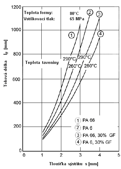
Of the processing parameters mentioned above, mould temperature has the least influence on the flow behaviour of plastic melts. From a rheological perspective, mould temperature influences the flow of the polymer melt, including its instantaneous temperature. Depending on the specified mould temperature and injection pressure, diagrams can be plotted – see Figure 15 – defining the minimum wall thickness of the moulded part that allows the plastic melt to fill even the most distant local feature in the mould cavity without difficulty. The distance is measured from the gate into the mould cavity.
 |
|
| Fig. 15 : Dependence of moulded part wall thickness on the rheological properties of polymer melts for different types of PA |
When discussing MFI values and the flowability of polymer melts, for the sake of completeness it is necessary to briefly mention the spiral flow test for polymer melts, which, like MFI values, can be used (with an understanding of their limitations) to compare materials suitable for injection moulding with one another.
Spiral flow testing of polymer melts is a purely processing-based test that allows the flow behaviour of polymer melts to be assessed under conditions that are practically identical to those during actual injection moulding. In addition, it also provides an opportunity to examine the effect of changes in processing parameters or, for example, the subsequent addition of additives on changes in the flowability of the polymer being assessed (addition of additives = a physical mixing process in which additives are added to the base polymer).
The spiral flow test is performed directly on an injection moulding machine. Under defined processing conditions, the polymer melt is injected into the centre of a mould whose cavity consists of a flat Archimedean spiral of theoretically infinite length and a specified cross-section – width x height. The processing conditions for the test are selected so that the spiral is not filled along its entire length. The measure of flowability is the spiral length – see Figure 16. A major drawback of the test is its subjectivity, because the cross-sectional dimensions of the spirals are not standardised and evaluators may use different cross-sections, making comparisons impossible. When evaluation is carried out using one specific spiral, it is a highly conclusive method.
 |
|
| Fig. 16 : Spiral flow test for polymer melts – from left – mould cavity in the shape of an Archimedean spiral, material with a higher MFI value , material with a lower MFI value |
In specific cases, the flow properties of a particular grade of pellets, expressed by the MFI, can be improved by adding a functional additive. For example, the requirements for the properties of the moulded part may necessitate the use of a material primarily intended for processing by extrusion, i.e. one with a very low melt flow index, usually up to approximately 2 g/10 minutes to 3 g/10 minutes at the temperature and load appropriate for the material in question. A low melt flow index usually also means that the resulting part has good mechanical properties. If such a material does not allow all geometries to be filled during injection moulding – for example, if the moulded part has very thin walls – its flowability, or MFI, can be modified and increased using a suitable functional additive.
The polymer melt flow index value also allows us to assess the potential effect on the flow properties of polymer-matrix composites, in which fillers, depending on their quantity, shape and size, affect not only the mechanical, electrical and thermal properties, which applies particularly to reinforcing fillers; particulate fillers are usually used as a cheaper substitute for a more expensive polymer material and, to a lesser extent, to improve properties, but also the dispersion of fillers and additives in the polymer melt or in the pellets of the injection moulding material concerned.
 |
|
In general, a polymer matrix with a high MFI can help to effectively disperse and distribute fillers and additives with good compatibility, or mutual miscibility. By contrast, a polymer with a low MFI leads to poor dispersion and insufficient compatibility with fillers. Similarly, the MFI value can also be affected by blending recycled polymer materials with virgin polymer materials obtained from their manufacturer, particularly when the recycled material – especially regranulate - has a low molecular weight compared with the original, non-recycled polymer material.
To refresh our memory, I would like to set out here four basic conditions that define a recycled plastic material:
- it is produced from plastic collected for recycling, has a market value or is supported by a legislative requirement
- it can be processed commercially – through recycling processes
- it is sorted and aggregated, grouped into defined streams for recycling processes
- recycled plastic becomes a raw material suitable for manufacturing new products
As recyclable and biodegradable plastics have also been discussed extensively recently, I will also provide definitions of degradability for these materials - a material or final product is considered biodegradable if it decomposes completely after disposal, usually within one year. Biodegradable materials may be partially or entirely derived from plants, although some petroleum-based plastic products can also be modified to achieve biodegradability. Some biodegradable materials are also compostable, meaning that they can decompose into a soil amendment, typically within six months. The composition of such materials is specified in the standards ASTM (American Society for Testing and Materials) D 6400, D 6868, including EN 13432.
MFI testing is crucial for determining how the recycling process affects material quality. The melt flow index may decrease, meaning that the material becomes more viscous and more difficult to process, or, more often, increase, i.e. the recycled material generally flows more readily and is easier to process, but has reduced performance properties.
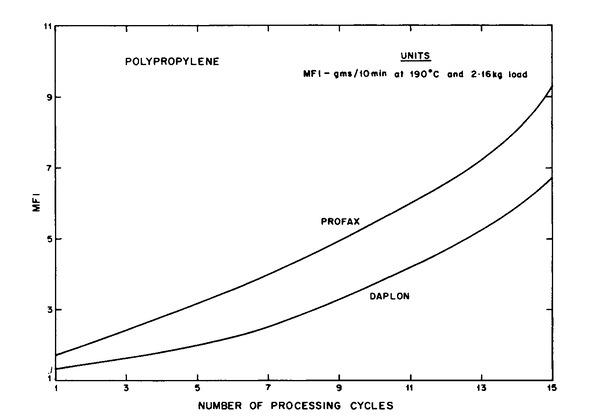
During mechanical recycling – usually using various types of mills, most commonly knife mills – followed by regranulation, with the option of adding additives – for example colour masterbatches, antistatic agents, various stabilisers, etc. – the pellets or regrind undergo thermal and shear stress for the third time – the first was during their production, the second during the initial production of injection-moulded parts, and the third during regranulation, for example on a twin-screw extruder, an extrusion machine with a pelletising die and a rotary knife for cutting the extruded strands, and further cycles will follow during the production of injection-moulded parts and subsequent regranulation, which can continue to be repeated. Such thermal and shear degradation significantly increases the MFI values of regranulates, while oxidative degradation can increase them further. Figure 17 shows the change in MFI as a function of recycling cycles for two types of extrusion-grade polypropylene.
 |
|
| Fig. 17 : Change in MFI ( MFI ) as a function of the number of regranulation cycles for two types of extrusion-grade polypropylene |
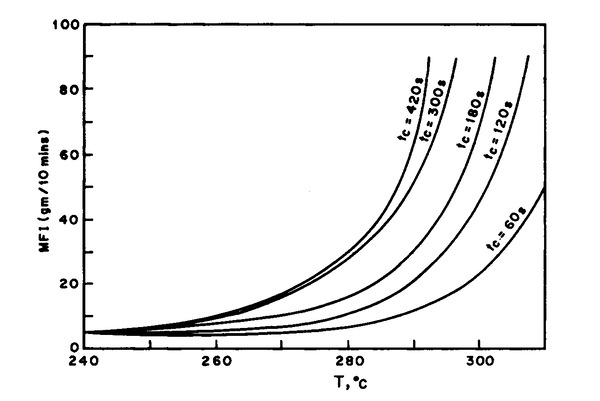
The measured MFI values of composites and their constituents are important not only in terms of temperature parameters and residence time at the processing temperature – thermal stress – but also in terms of shear stress during polymer melt preparation, when setting the plasticising parameters – screw back pressure, screw peripheral speed and the resulting screw rotational speed – which, among other things, also affects the dispersion of fillers and additives in the polymer melt, including the reduction in length of fibrous fillers. Higher parameter values in the plasticising phase of the injection moulding process improve dispersion on the one hand, but increase the shear stress on the polymer melt on the other. Figure 18 shows an example of the change in MFI as a function of the material's residence time at the processing temperature.
 |
|
| Fig. 18 : Effect of temperature and residence time at the processing temperature on MFI for PP |
|
For example – the MFI of recyclate from a PET bottle (MFI = 145 g/10 min under the given test conditions) is approximately five times higher than that of standard injection-moulding-grade PET pellets (MFI = 32 g/10 min, same test conditions). The reason is the reduction in molecular weight due to hydrolytic degradation during mechanical recycling. This adverse effect on the MFI of recycled PET can be addressed during recycling by adding a functional additive that extends the macromolecular chains. Chain extension has also proved effective in increasing the molecular weight of standard PET pellets. A similar reduction in MFI was observed in the biodegradable polyester PLA (PLA, polylactic acid). A macromolecular chain extender is also used to increase its molecular weight. Selecting an unsuitable chain extender can lead to an increase in MFI because it acts as a plasticiser.
As already mentioned, during the processing of polymer materials by injection moulding, the injected material is exposed to temperatures, oxidative degradation and shear degradation, which can cause molecular chain scission and thus a reduction in molecular weight. A decrease in molecular weight is generally characterised by changes in the MFI of the pellets concerned.
It follows from the above that the change in the polymer melt flow index during the injection moulding of a specific part can also serve as a quality control value for assessing the quality of that part, or of its injection moulding process and optimally set technological process parameters. Such indirect assessment of the quality of injection-moulded parts is advantageous for materials prone to degradation, particularly shear degradation (in addition to polymer melt preparation in the plasticising barrel of the injection moulding machine, the filling of the mould cavity through the injection mould's runner system, especially the gate, is also checked). From the MFI value determined during the injection moulding of an OK part, which was assessed on the basis of the prescribed quality criteria, and compared with the MFI value determined when offcuts from the newly produced part pass through a capillary viscometer, it is possible to infer whether the molecular weights of the two parts are comparable (they have the same MFI, or are within the specified tolerance range) and therefore whether their quality characteristics will also be the same.
End of the fourth part. The final part will follow on 27. 12. 2024
You can find the first part here.
You can find the second part here.
You can find the third part here.
Illustrative photo: AI
-

Jiří Češka, Nástrojárna Příbram
Production of injection molds, cutting and stamping tools, CNC machining, electric discharge machining, laser welding.

Suppliers on this topic
-

Plasted spol.s r.o.
Plastic processing, production of plastic products, production of plastic windows, plastic window profiles, plastic… -

KOH-I-NOOR MACHINERY a.s.
Development and production of tools, injection molds, blow molds, plastic injection, blow molding machines for… -

Mateja Plasty, s.r.o.
Processing of thermoplastics and thermosetting plastics using injection molding, extrusion and blow molding. -

Elektroplast výrobné družstvo Prešov
Production of plastic products, injection, vacuuming of plastics, plastic technical moldings, household goods. -

Extruindustrie CR s.r.o.
Extrusion of plastics, production of plastic profiles, plastic profiles, boards, rods and others, plastic and rubber… -

JASPLASTIK-SK spol. s r.o.
Plastic components for the automotive, electronic and industrial markets, plastic molding, assembly, painting, PVD…



ALLROUNDER e TREND: ARBURG Sets a new standard in electric injection moulding machines
21.9.2026 Rising energy costs, pressure to improve production efficiency and a shortage of skilled workers are changing how plastics processors assess new investments. ARBURG is responding to these trends with the launch of its new ALLROUNDER e TREND series...



Most read in the last 7 days
-
Polymer prices - october price increases partly successful, with minor corrections expected in the week ahead
-
Long-lasting solution: Radiation-crosslinked PE-Xc pipes for drinking water supply
-
Polymer prices – the increase in olefin monomer contract prices in October was in line with expectations
-
Polymer prices - Year-End Polymer Price Scenarios
-
Plastica-expo 26







Most read in the last 7 days
-
Polymer prices - october price increases partly successful, with minor corrections expected in the week ahead
-
Long-lasting solution: Radiation-crosslinked PE-Xc pipes for drinking water supply
-
Polymer prices – the increase in olefin monomer contract prices in October was in line with expectations
-
Polymer prices - Year-End Polymer Price Scenarios
-
Plastica-expo 26