





Ing. Lubomír Zeman: Melt flow index and its use in thermoplastic injection moulding technology - theory and practice part 3

Definition of MFI and the resulting applications and limitations
The melt flow index is defined in terms of how it is measured - as the mass or volume of the material being tested that flows through a die of defined shape and dimensions over a period of 10 minutes, under a specified load and at a temperature appropriate to the granules being tested. Since the test parameters are clearly specified – temperature, load, die diameter and length – the shear stress is also determined. The melt flow index is therefore only a single point on the viscosity curve, determined at a shear rate that is substantially lower than the lowest shear rate encountered in actual injection moulding.
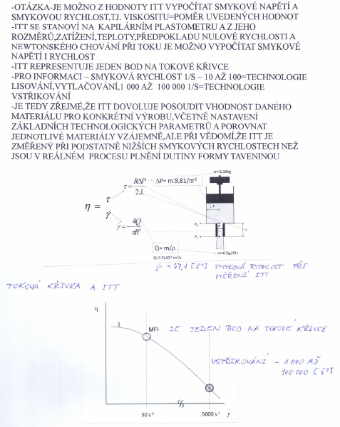
The question is – can MFI values be used to calculate shear stress and shear rate, or viscosity, which is the ratio of these values? As I will explain below, the melt flow index is determined by measurement using an extrusion capillary plastometer, and its value, the load used in the test and the test temperature can be used to calculate both shear stress and shear rate, assuming zero velocity and Newtonian flow behaviour – Figure 10. To give an idea – MFI is measured at very low shear rates, compression moulding and extrusion processes take place at shear rates of approximately 10 s-1 to 100 s-1 , and injection moulding of thermoplastics can take place within a shear rate range of approximately 1 000 s-1 to approximately 100 000 s-1
 |
|
| Fig. No. 10 : Calculation of the shear rate during MFI measurement and comparison of the shear rate during MFI measurement ( MFI ) and the shear rate during injection moulding |
It follows from the above that MFI is not suitable for describing the behaviour of polymer melts, but is a technological test which, bearing in mind that it is performed at substantially lower shear rates than those occurring in the actual injection moulding process when filling mould cavities with polymer melt (Figure 10), is suitable, for example, for:
- comparing materials with one another in terms of their flowability – the higher the MFI value, the greater the flowability of the melt; the melt flows more readily into the geometric features of the mould cavity, reproduces surface textures more accurately and flows more readily into thin walls, or it is possible to work with lower melt or mould temperatures, lower injection pressure or lower injection speed
- assessing the quality of a supplied batch of granules - if the melt flow index stated by the manufacturer on the batch inspection certificate does not correspond to the measured value, i.e. its flowability differs from the declared flowability, the mechanical properties of the supplied material will not meet the requirements either, because, like flowability, they depend on the size of the macromolecules
- comparing the effect of additives on flowability - low-molecular-weight substances, such as colour masterbatches, increase the flowability of materials, while fibrous fillers - glass fibres, of inorganic origin - significantly reduce flowability
- assessing the quality of the production process – a change – an increase - in the melt flow index determined from ground mouldings - recyclate, compared with the value stated in the certificate or the value measured on the virgin material, indicates thermal degradation of the material caused by unsuitable injection moulding parameters - high melt temperature, a long residence time of the material at temperature in the plasticising barrel, high shear stress during plasticising, etc.
- designing the feed system of injection moulds, particularly the gate size and the dimensions of the runner channels in injection moulds
- designing the geometry of the moulding
The method for determining the melt flow index of a thermoplastic can be used in engineering practice to assess the consistent quality of incoming material, to compare the flow behaviour of filled and unfilled thermoplastic melts, and also to assess the quality of the production process.
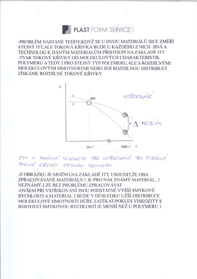
A problem arises when the same MFI is measured for two materials being compared, but each has a different flow curve, while the process engineer or machine setter has only the MFI values available. Figure 11 shows such an example:
 |
|
| Fig. No. 11 : MFI measurement – MFI and flow curves |
From Figure 11, or rather the measured MFI value, it can be concluded that, in terms of MFI, both injection moulding materials under evaluation can be processed using the same process parameters. However, as already mentioned several times, during the injection moulding of thermoplastics, their flow occurs at substantially higher shear rates, and the flow curves of the two materials indicate that material 2 will flow less readily due to its narrower molecular weight distribution and has higher viscosity values. This fact must therefore also be taken into account when setting the injection moulding process parameters, for example by setting a higher melt or mould temperature, higher injection phase parameters – speed, pressure – or possibly other parameters, depending also on the material being processed and the quality requirements for the moulded part.
The quality of the input material, i.e. its rheological, physical, thermal and other performance properties, primarily reflects the chemical composition of the plastic, its molecular structure, etc. The melt flow index provides an indication of the molecular weight and viscosity of the polymer material. If the melt flow index does not correspond to the values declared by the manufacturer ( for example in the quality certificate for the supplied batch of granules ), other performance properties set out in the material specification will not correspond either, because these, like flowability, depend on the size of the macromolecules.
The method cannot be used for thermoplastics whose rheological behaviour, as I have already mentioned, is affected by hydrolysis - the decomposition of compounds by water - or crosslinking. This applies particularly to certain types of PA, or possibly PC. For these materials, the viscosity number is specified.
Measuring the Melt Flow Index
The simplest capillary rheometer is a device for measuring the melt flow index (MFI). The design of the capillary viscometer and the principle of melt flow index measurement follow from its definition given in the previous section.
 |
|
| Fig. No. 12 : Diagram of a capillary extrusion rheometer for measuring MFI |
During measurement, granules, pellets, powder or offcuts of the material being tested are placed in an insulated cylinder maintained at the temperature specified for the material under evaluation. A piston located in the upper part of the cylinder is pressed down by a weight with a selectable mass, which is again specified for the material concerned. The volumetric flow rate of the polymer emerging from the capillary - die is determined; this is proportional to the viscosity of the material being measured (high viscosity = low MFI and vice versa) – see Figure No. 12 .
MFI (MFR) denotes the quantity of melt (in grams) that flows through a die with a defined diameter (2.095 mm) and length (8 mm) in 10 min under a defined load and at a defined temperature. This definition makes it clear that MFI represents only a single point on the flow curve.
The thermally insulated cylinder into which the charge of the material under evaluation is placed must be made of a material inert to the polymers being measured. The inner surface of the cylinder must be corrosion-resistant, its hardness must have a minimum value of 500 HV, and its operating temperature must be up to 450 °C. The cylinder is 115 mm to 180 mm long and has an internal diameter of 9.550 +/- 0.025 mm.
 |
|
The steel piston, which must form a so-called friction pair with the cylinder to prevent scuffing when subjected to the defined weight and moving downwards during extrusion of the molten polymer material, has a head with the dimensions shown in Figure No. 12, and its shank is reduced to a diameter of approximately 9 mm. The piston head must be thermally insulated from its shank and the weight.
The die is usually made of tungsten carbide, with a maximum ovality of the cylindrical section of 0.005 mm over its entire length. It must not protrude beyond the lower edge of the cylinder and must be coaxial with the cylinder axis.
Before the test, both the piston and the internal surfaces of the cylinder and die must always be thoroughly cleaned. The temperature of the instrument must be stabilised before the test sample is inserted, i.e. before measurement begins, the instrument must be maintained at the operating temperature without a sample for a certain period of time (approximately 15 minutes).
After the sample has been quickly inserted, it is left without a load for a certain period – approximately 4 minutes to 6 minutes. Once the weighted piston applies the load, the molten material is extruded through the die into the free space below the instrument's barrel, and the resulting strand is progressively cut off either by the operator or automatically (the first portion of the strand); any portions of the strand containing bubbles are removed and are not evaluated – they are not weighed. At least three cut-offs should be weighed, to an accuracy of 0,001 g.
The mass of the charge of the material being evaluated usually ranges from 4 g to 8 g.
Interchangeable weights – manually or automatically – the mass of the piston is also included in the test load – the selected nominal load should have an accuracy of 0,5 %.
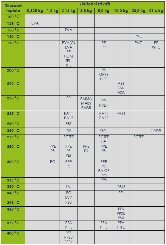
The test conditions – temperature, mass of the weights – are standardised or agreed contractually for individual material groups and must always be stated together with the MFI value – for example, MFI = 16,4 g/10 minutes (230 °C/2,16 kg). The recommended parameters are given in Table 1:
 |
|
| Table 1: Recommended temperature and load values for determining MFI ( MFR ) for selected thermoplastics |
|
 |
|
| Table 2 : Conditions for measuring the melt flow index |
I have already mentioned that the standard ČSN EN ISO 1133-1:2012 Plastics – Determination of the melt mass-flow rate (MFR) and melt volume-flow rate (MVR) specifies two methods, A and B, for determining MFI.
Method A :
The principle of this method is to measure the time taken to extrude the melt through a die of specified dimensions over a specified distance travelled by the loaded piston. The piston travel is measured to an accuracy of ± 0,1 mm and the time (10 minutes) to an accuracy of 0,1s. The extruded strand is progressively cut off, and the time for each cut-off is measured and added together. The result of the measurement is the melt mass-flow rate, expressed by the equation
MFR ( T,m-nom ) = t ref . m / t
where: T- is the melt test temperature [°C] – see Table 1, m-nom - nominal load [kg] – see Table 1, m - average mass of the cut-off[g], tref - reference time ( 10 min = 600 s ) [s] and t - cut-off interval [s].
Method B :
Unlike Method A, Method B allows not only the melt mass-flow rate MFR but also the melt volume-flow rate MVR to be determined, provided that :
a) the time during which the piston travels a specified distance is measured
or
b) the distance travelled by the piston during a specified time is measured
The result according to a) or b) is expressed by the equations:
MFR ( T,m-nom) = S . t ref .l . ρ / t = 427 . l . ρ / t
MVR ( T,m-nom ) = S . t ref . l / t = 427 . l / t
where: T - melt test temperature [°C], m-nom – nominal load [kg],
tref - reference time (10 min = 600 s) [s], S – average cross-sectional area of the piston and barrel [cm2],
t - specified measurement time (see a) or the average value of the individual time measurements (see b) [s], l - specified distance travelled by the piston (according to point b) or the average value of the individual distance measurements (according to point a) [cm], ρ - melt density at the test temperature [g/cm3 ], m - mass determined by weighing the strand extruded by the piston travelling over distance l, to an accuracy of 0,001 g.
When determining MFR using this method, it is necessary to know the density of the thermoplastic melt, which can be expressed by the following relationship:
ρ = m / 0,711 . l
Where m is the mass [g] determined by weighing the strand extruded by the piston moving over a distance l [cm]
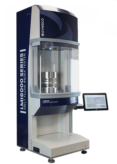
Figure 13 shows the latest type of production-use capillary extrusion plastometer from Dynisco. Within the variants offered, the manufacturer allows the buyer to configure the instrument to their own requirements, choosing, for example, between measurement using method A or both methods A and B, and loading weights using a lifting platform or an electromechanical lifting mechanism that automates weight lifting. It also offers a choice of barrel material, the option of operation with or without automatic cutting of extrudate samples of the material being evaluated, including procedures in accordance with ČSN EN ISO 1133 and ASTM D1238, or certification for materials sensitive to time-temperature history or moisture in accordance with ČSN EN ISO 1133-2. The hardware and software configuration allows, for example, measurement to be started with a single press of a button, eliminating the need for complex settings and simplifying the entire testing process.
 |
|
| Fig. 13: Dynisco capillary extrusion plastometer – LMI6000 Series model, main dimensions – base 46 x 54 cm, height 130 cm, weight including weights 136 kg, of which the weights according to the ISO standard account for 21,6 kg |
In addition to melt mass-flow rate values, the measurements performed and their results can also be used to determine the FRR ratio, which can be used to evaluate, for two measured pellet samples, the effect of molecular weight distribution on their rheological behaviour, the flow behaviour of polymer melts. Polymers with higher molecular weights achieve higher strength, stiffness, lower toughness and also higher viscosity, which means that they have lower flowability, and the injection moulding process parameters must be adjusted accordingly. Again, this involves a comparative assessment of two materials.
The FRR ratio is calculated as follows:
FRR = MFR1(T,m-nom) / MFR2(T,m-nom) < 1
During the preparation of polymers – synthetic polymers are formed through three basic chemical reactions: polymerisation, polycondensation and polyaddition – chains of different lengths are formed. This is due to the statistical distribution of energy conditions during their formation, so not all macromolecules formed under given polymerisation conditions are of the same size, and the polymer consists of varying numbers of structural units. A polymer is therefore a collection of macromolecules with different numbers of structural units and different macromolecular lengths.
Polymers are polydisperse substances (polydisperse = a dispersed system containing particles of many different sizes, characterised by a continuous distribution curve), and therefore the degree of polymerisation differs between individual fractions, as does the molecular weight of the polymeric substances in the individual fractions. The proportion of macromolecules of a given molecular weight in a polymer-homologous mixture is characterised by a distribution curve. Molecular weight is usually defined by an average value. The number-average, weight-average or viscosity-average molecular weight is determined. The number-average molecular weight Mn is defined as the ratio of the sum of the molecular weights of all molecules to the total number of molecules. Number-average molecular weight values are sensitive to the presence of small amounts of low-molecular-weight fractions. The weight-average molecular weight Mw is related to the mass of the molecules in the individual fractions. Weight-average molecular weight values are sensitive to high-molecular-weight fractions. The terms are explained using the example distribution curve in Figure 14:
 |
|
| Fig. 14: Example of a distribution curve for a polymer material |
A polymer material with a lower molecular weight allows higher injection speeds to be used in injection moulding, has lower viscosity and higher flowability. A polymer with a higher molecular weight will be processed at a lower polymer melt flow rate; the melt has higher viscosity and therefore lower flowability. The melt flow rate is an indirect measure of the relative average molecular weight.
Molecular weight, dispersity and branching have a significant influence on the mechanical and physical properties of polymers. In general, higher molecular weight improves mechanical properties, i.e. tensile strength, yield strength and impact toughness increase. However, as already mentioned, higher molecular weight also increases the melting and glass transition temperatures and melt viscosity, making the polymer material more difficult to process and shape.
Dispersity, the degree of dispersion or spread, has the opposite effect; a broader molecular weight distribution reduces tensile strength and impact toughness but increases yield strength, or in other words, lower dispersity ( a narrower molecular weight distribution ) leads to better mechanical properties. The low-molecular-weight portion of the distribution has a similar effect to a plasticiser, i.e. it reduces brittleness, increases toughness and reduces melt viscosity, which improves processability, while the high-molecular-weight portion causes processing difficulties because it makes a large contribution to melt viscosity.
Branched macromolecules have short side substituents (elements replacing the original elements during substitution, replacement or exchange) attached to their backbone, which impair their mobility. Branching of macromolecules causes them to move further apart, reducing the forces between macromolecules and thus also reducing mechanical strength, hardness and elastic modulus.
End of Part Three. To be continued on 20. 12. 2024
You can find the first part here.
You can find the second part here.
Illustrative photo: AI
-

Jiří Češka, Nástrojárna Příbram
Production of injection molds, cutting and stamping tools, CNC machining, electric discharge machining, laser welding.

Suppliers on this topic
-

Plasted spol.s r.o.
Plastic processing, production of plastic products, production of plastic windows, plastic window profiles, plastic… -

KOH-I-NOOR MACHINERY a.s.
Development and production of tools, injection molds, blow molds, plastic injection, blow molding machines for… -

Mateja Plasty, s.r.o.
Processing of thermoplastics and thermosetting plastics using injection molding, extrusion and blow molding. -

Elektroplast výrobné družstvo Prešov
Production of plastic products, injection, vacuuming of plastics, plastic technical moldings, household goods. -

Extruindustrie CR s.r.o.
Extrusion of plastics, production of plastic profiles, plastic profiles, boards, rods and others, plastic and rubber… -

JASPLASTIK-SK spol. s r.o.
Plastic components for the automotive, electronic and industrial markets, plastic molding, assembly, painting, PVD…



ALLROUNDER e TREND: ARBURG Sets a new standard in electric injection moulding machines
21.9.2026 Rising energy costs, pressure to improve production efficiency and a shortage of skilled workers are changing how plastics processors assess new investments. ARBURG is responding to these trends with the launch of its new ALLROUNDER e TREND series...




Most read in the last 7 days
-
Polymer prices - october price increases partly successful, with minor corrections expected in the week ahead
-
Polymer prices - Year-End Polymer Price Scenarios
-
Long-lasting solution: Radiation-crosslinked PE-Xc pipes for drinking water supply
-
Polymer prices – the increase in olefin monomer contract prices in October was in line with expectations
-
Plastica-expo 26






Most read in the last 7 days
-
Polymer prices - october price increases partly successful, with minor corrections expected in the week ahead
-
Polymer prices - Year-End Polymer Price Scenarios
-
Long-lasting solution: Radiation-crosslinked PE-Xc pipes for drinking water supply
-
Polymer prices – the increase in olefin monomer contract prices in October was in line with expectations
-
Plastica-expo 26