


3DTEC s.r.o.: Use of 3D Measurement in Mold Optimization
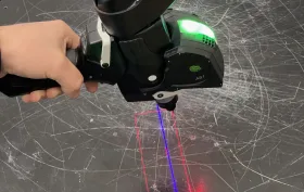
Injection mould – the foundation of plastics manufacturing
Injection moulds are a fundamental element of manufacturing processes in the plastics industry. Their precise design and high-quality construction are key to producing plastic parts with high dimensional and geometric accuracy. Mould quality is directly reflected in the final product and affects both production efficiency and costs. In this context, 3D measurement and scanning play an indispensable role in mould design, inspection and optimisation.
Choosing the right 3D scanner
If only a moulded plastic part is available initially, for which a mould needs to be reverse-engineered, 3D scanning can significantly streamline the design process. The first step is to choose a suitable type of scanner, which depends on the size of the part and the required measurement accuracy. In practice, structured-light optical scanners or laser scanners are most commonly used. Laser scanners can handle even shiny or dark surfaces without the need for matting sprays or photogrammetric markers. Camera-based scanners, on the other hand, provide a higher level of detail but require surface preparation before scanning.
Laser scanning generates a digital model in the form of a point cloud that accurately captures the surface geometry. These data are then converted into a 3D mesh, with noise removal, surface smoothing and data volume optimisation. Missing sections of the scan can also be filled in if necessary. The mesh prepared in this way then serves as the basis for creating a solid 3D model using reverse engineering methods.
| Fig. 1 Point cloud | Fig. 2 Polygon model | Fig. 3 Solid model |
How to manufacture a reliable injection mould using 3D measurement
A prototype is usually created before production of the final mould begins. Its accuracy can be verified by comparing a 3D scan with the CAD model, allowing dimensional or geometric deviations to be identified and eliminated at an early stage. This significantly increases the likelihood that the final mould will function correctly from the outset. Manufacture of the mould itself then proceeds on the basis of the optimised 3D model and simulation analyses, with the choice of technology – CNC machining, electrical discharge machining or 3D printing – depending on the complexity of the mould and the materials used.
|
Mould manufacturing is usually an iterative process. At each stage, 3D measurement can be used to verify dimensional accuracy and compare the actual condition with the design data. Moulds are generally manufactured with a machining allowance – whether this is sufficient can be assessed precisely using a 3D scanner. Obtaining information on the actual allowances enables machining parameters to be optimised, reducing the production of defective parts, lowering material consumption and increasing production efficiency.
Once the mould is completed, a final 3D scan is performed for geometry inspection and calibration. This step verifies whether the finished mould matches the original design and meets the specified tolerances. If deviations are detected, they can be corrected quickly and precisely on the basis of accurate 3D data, significantly reducing the time needed for final fine-tuning.
|
The digital model of the finished mould is then used not only for archiving but also for predictive maintenance. It enables mould wear to be monitored during operation, its service life – in other words, the number of production cycles – to be estimated more accurately, and maintenance or replacement to be planned efficiently. This helps reduce scrap rates, limit unplanned downtime and ensure greater production stability.
A practical example: the automotive industry uses 3D scanning to reconstruct moulds
Automotive industry – reverse engineering a headlight cover: An automotive parts manufacturer needed to create a new mould based on an older moulded plastic headlight cover for which technical documentation no longer existed. The moulded part was scanned using a 3D scanner, then converted into a CAD model and further modified to reflect current production requirements. Thanks to the accuracy of the scanning, there was no need to create a physical prototype – the mould could be manufactured directly and subsequently put into production successfully.
Why 3D measurement is an integral part of modern injection mould manufacturing
Today, 3D measurement is not just an inspection tool but an active element of optimisation and the decision-making process. It enables not only the precise manufacture of new moulds but also modifications to existing ones, maintenance planning and the minimisation of production risks. In the era of digitalisation and Industry 4.0, it is thus becoming a key partner for efficient, high-quality and predictive production.
Would you like to make injection mould manufacturing more efficient using 3D technologies? Do not hesitate to contact us – we will be happy to help you find the optimal solution.
-

3DTEC s.r.o.
Accredited testing services for various industries, 3D measurement, 3D scanning, programming for 3D measurements.

Suppliers on this topic
-

MEPAC SK, s.r.o.
Maintenance of injection molds, tool repair, lapping, grinding, polishing, laser welding, surfacing, engraving, tool… -

3D Tlač - Stepanek3D
3D scanning, 3D printing, editing of 3D models, plastic atypes, custom production, small series production, production… -

ADATEX, s.r.o.
3D printing, 3D printers, 3D scanners, 3D scanning and inspection, 3D digitization, 3D measurement, 3D model, 3D… -

technology-support s.r.o.
CAD/CAM supplies for CNC machine tools, CAD/CAM solution GibbsCAM and Cimatron, CAD solution ZW3D, high-pressure and… -

TECHNI-SCAN s.r.o.
3D scanning and inspection, 3D modeling, reverse engineering, industrial measurements, CNC metalworking, metrology. -

OSMOS s.r.o.
ERP software, 3D design of plastic products, simulation of plastic injection, plastic press, plastic injection…


DESMA Open House 2026: Innovation, Practical Application, and International Exchange
28.10.2026 Under the motto “Built right. Runs right.”, DESMA opened the doors of its main plant in Fridingen on October 1, 2026, and welcomed over 280 visitors from around the world to a thoroughly successful Open House.


Most read in the last 7 days
-
Polymer prices - october price increases partly successful, with minor corrections expected in the week ahead
-
Long-lasting solution: Radiation-crosslinked PE-Xc pipes for drinking water supply
-
Polymer prices – the increase in olefin monomer contract prices in October was in line with expectations
-
Polymer prices - Year-End Polymer Price Scenarios
-
Plastica-expo 26




Most read in the last 7 days
-
Polymer prices - october price increases partly successful, with minor corrections expected in the week ahead
-
Long-lasting solution: Radiation-crosslinked PE-Xc pipes for drinking water supply
-
Polymer prices – the increase in olefin monomer contract prices in October was in line with expectations
-
Polymer prices - Year-End Polymer Price Scenarios
-
Plastica-expo 26