


Algorithmic design of cooling structures using additive manufacturing
Introduction
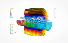
For several years, CARDAM s.r.o. has been developing and refining an algorithm for generating optimal heat exchange systems that make maximum use of the advantages of additive technology. These systems enable controlled tool behaviour in the key area of heat exchange, which has a fundamental impact on production productivity and quality. The algorithm is based on the concept of mathematical TPMS structures (Triply Periodic Minimal Surfaces), whose parameters are directly dependent on the simulation of the temperature field in the tool and whose response can be adjusted to suit the requirements of the process. The algorithm can also automatically perform all post-processing of the final geometry, and the resulting data can be processed directly by any suitable printer without further modifications. The result is the elimination of the shortcomings of conventional systems and an increase in the overall efficiency of the injection moulding or casting process. As this is a universally applicable solution (the shape of the structures can be linked, for example, to a structural simulation or flow analysis), it can be used in many other industrial sectors, for example in the design of lightweight components, etc.
The extensive experience of CARDAM s.r.o., which has long been involved in optimisation projects at the foundry in cooperation with BENEŠ and LÁT a.s., repeatedly confirms that the behaviour of the tool in terms of the temperatures reached during the cycle is crucial to the quality of the casting or injection-moulded plastic part. For this reason, considerable effort is devoted to fine-tuning melt temperatures, cycle times and mould cooling/temperature control. Particularly for parts with complex geometries or other characteristics that are unfavourable from a processing perspective, however, process engineers have to contend with numerous adverse factors that make it difficult to achieve optimal process settings. Additive manufacturing therefore began to be used to good advantage in tool design and manufacture years ago. By using it, we can take an unconventional approach to the design of mould cooling and temperature control systems, thanks to greater design freedom.
The principle of additive manufacturing, or 3D printing, consists of gradually adding material layer by layer and joining it only where necessary. The addition of material fundamentally distinguishes additive manufacturing from more common subtractive methods, in which material is removed (typically machining). The principle of additive manufacturing provides significantly greater flexibility in terms of the geometries that can be produced. A wide range of materials can currently be printed, including polymers and metals, as well as wax and sand. In toolmaking, geometric flexibility can be used primarily to create shape-adapted (conformal) heat exchange systems.
| Fig. 1: DMLS, SLM additive technologies (reproduced from formnext AM Field Guide 2022) | |
The most common additive technology used in practice to manufacture parts of casting or plastics moulds is Direct Metal Laser Sintering (DMLS); Selective Laser Melting (SLM) is also used, with both methods based on the same principle. Fig. 1 shows a schematic diagram. Metal material (in this case tool steel) in powder form is applied layer by layer to the build platform using a recoater blade. The thickness of a single layer is in the tens of μm. The deposited material is then sintered using a laser.
The most common type of conformal cooling (temperature control) involves routing a channel, usually with a circular cross-section, that follows the functional surface of the mould insert as closely as possible. The design of a suitable channel depends to a large extent on the experience of the tool designer and the process engineer at the foundry or injection moulding plant. Fig. 2 shows an example of conformal cooling. Its final design and functionality should be verified using suitable simulation software.
A disadvantage of metal 3D printing is its still relatively high cost. For this reason, material must be used as efficiently as possible and machine time during printing must also be reduced, for example by using topology optimisation where the application permits.
| Fig. 2: Example of a conformally cooled mould insert | |
Topology optimisation is a computational algorithm that, based on specified loads, boundary conditions and constraints, maximises material utilisation and reduces material where it is not needed, while maintaining the component's functionality and performance characteristics. This produces a geometry, often highly free-form, which may be impossible to manufacture using conventional manufacturing technologies, whereas such a part need not pose an obstacle to additive manufacturing.
Topology-Optimised Tool
CARDAM s.r.o. continuously develops the CARDAM Simul computational environment. It is an analytical tool that links multiple Open Source solvers through a core algorithm, enabling the analysis of multiphysics problems. Topology optimisation, somewhat unusually based on the finite volume method (FVM), is also one of its functions.
The BENEŠ a LÁT a.s. foundry approached CARDAM s.r.o. to create conformal cooling in a tool for a zinc alloy casting. The primary objective was to shorten the cycle time while maintaining the internal quality of the part. Given the planned installation of the mould on a machine requiring a mould with clamping dimensions of 102×102 mm, additive manufacturing was selected for the entire tool. For the reasons outlined above, the design was subjected to a topology optimisation algorithm in the CARDAM Simul environment. The mould geometry consists of two types of regions: the first comprises volumes that
must remain unaffected by the algorithm (the casting cavity, centring and fastening points, cooling connection locations, etc.), while the second comprises the volume of material that can be modified. The algorithm's procedure is shown schematically in Fig. 3 and Fig. 4.
| Fig. 4: Resulting topology-optimised geometry | |
The computation takes into account the specified boundary conditions (fastening in the machine, loading). Material is progressively added or removed and redistributed until the specified condition is met, for example maximum strength for a given volume. This produces a highly free-form geometry that nevertheless meets all functional requirements. The final mould shape undergoes detailed structural analysis using the finite element method (FEM) and verification of casting parameters in the MAGMA software environment.
The data prepared in this way was passed on for additive manufacturing. The components were printed from DIN 1.2709 tool steel using DMLS technology on an EOS M290 machine from the BENEŠ a LÁT a.s. foundry's machine fleet at the Z02 Poříčany plant. One of the printed components, still on the build platform, is shown in Fig.7.
The mould core was manufactured using a so-called hybrid approach, in which the base was machined and only the functional shaped section, incorporating conformal cooling channels, was additively printed onto it. The core is shown in Fig. 7.
|
Fig. 5: Additively manufactured mould half on the build platform, |
||||
Thanks to topology optimisation, the tool's weight was reduced by 54 % compared with the solid geometry, shortening the printing time by a third. The casting production cycle time was reduced by 15 % compared with the previous conventionally manufactured mould, and the usual internal defects in the part were also eliminated, resulting in an increase in its tested load-bearing capacity.
Use of Variable Heat-Exchange TPMS Structures
In addition to conformal channels, additive technologies also enable the use of sophisticated structured solutions. CARDAM s.r.o., in cooperation with the BENEŠ a LÁT a.s. foundry and the Institute of Physics of the Czech Academy of Sciences, v.v.i., and with support from the TAČR Théta programme, developed an algorithm for generating structures directly linked to the simulation of the mould's temperature field during casting or injection moulding. This resulted in a unique computational tool that enables us to create heat-exchange systems that behave according to specified requirements (the most uniform heat transfer possible, directing the cooling gradient, etc.).
The algorithm is based on mathematical structures known as Triply Periodic Minimal Surfaces (TPMS). Their advantages are their suitability for additive manufacturing and, above all, the ability to define these structures using an implicit function. First, a preliminary selection of structures was carried out, during which these structures were virtually tested with regard to heat transfer properties, pressure losses and mechanical load-bearing capacity. A total of 3 TPMS structures (Schwarz P, Gyroid, Diamond) were tested, along with a BCC lattice structure for comparison. Examples of simulations for the gyroid variant are shown in Figs. 8 and 9. The next stage of simulations focused on tuning the parameters of the individual structures (period size, wall thickness).
The procedure described above was applied to the production of a die insert for a casting made by high-pressure die casting of an aluminium alloy (see Fig. 10). The problematic area can be seen in Fig. 11. This is a location that is difficult to cool, which primarily leads to longer cycle times.
| Fig. 8: Example of flow analysis using a synthetic approach |
Fig. 9: Visualisation of the overall results (period 6 mm, wall thickness 1,0 mm) |
| Fig. 10: Casting from the die under investigation | Fig. 11: Problematic area of interest |
Due to its size, the insert forming the problematic part of the casting would not fit into the printer's build volume, so it was divided into two parts. Hybrid printing was again used in production, see Fig. 12. Only the left-hand part was printed onto the base, and a cooling structure was placed in the marked section.
| Fig. 12: Insert drawing | |
To establish the relationship between the structure parameters and the thermal conditions in the tool, a simulation was performed in the OpenFOAM environment, which is implemented in the CARDAM Simul solver. The casting geometry prepared for simulation, including the cooling and temperature-control channels, is shown in Fig. 13. Heat transfer between the die and the fluid in the cooling and temperature-control channels (or the melt) is represented by convection at the boundary-condition level, defined by the bulk fluid temperature and the heat transfer coefficient. The simulation result is presented in Fig. 14.
| Fig. 13: Layout of the casting with the gating system and channels (the internal structure region is shown in yellow) |
Fig. 14: Thermal analysis results (temperature at the boundary conditions) |
Based on comparative analyses of the structures, the results concerning the temperatures achieved were converted into parameters defining the geometry of the structure, thereby varying its heat transfer capability throughout its volume. The result is a continuously varying structure (see Figs. 15 to 18).
| Fig. 15: Resulting structure, inserted into the printed part of the die |
Fig. 16: Resulting structure section y = 0 |
| Fig. 17: Resulting structure section y = -1 mm |
Fig. 18: Resulting structure section y = -2 mm |
The final CAD representation of the insert is shown in Fig. 19. Only the yellow part was produced using additive manufacturing (hybrid approach).
| Fig. 19: Final CAD model of the insert with a variable internal structure | |
The simulations performed confirm the significant benefits of structured cooling in terms of its efficiency.
The data presented show that temperatures at the surface of the body decrease significantly faster, in this particular case by more than 50 % over the same period, see Figs. 20 – 22.
| Fig. 20: Temperature field on the surfaces of the bodies t = 183 s |
Fig. 21: Temperature field on the surfaces of the bodies t = 200 s |
Fig. 22: Temperature field on the surfaces of the bodies t = 250 s |
The final form of the body, including a view of it in operation, is shown in Figs. 23 and 24. 3D printing was followed by heat treatment (precipitation hardening), EDM finish machining and fitting to the surrounding mould components. Deployment in production confirmed the benefits of structured cooling and, after the parameters were fine-tuned based on thermal imaging measurements, demonstrated good agreement with the simulation.
| Fig. 23: Final insert | Fig. 24: Insert in operation |
Conclusion
The examples above demonstrate that additive manufacturing already has its place in toolmaking practice. Conformal cooling enables defect-free production even of highly complex castings with non-ideal shapes, without any compromises; topology optimisation, in turn, primarily contributes to the cost-effectiveness of manufacturing such tools. Today, additive manufacturing can undoubtedly be recommended as a technology worth keeping in mind when designing tools for customers. The advantages of conformal cooling are indisputable, and an appropriate approach to tool design also brings economic benefits. The resulting algorithmic solution can be applied not only to heat exchange, but also in other areas, such as the design of lightweight, structurally loaded parts. CARDAM s.r.o. has extensive know-how both in additive manufacturing and in mathematical calculations and toolmaking for casting moulds and plastics moulds. This enables it to offer customers comprehensive services not only in the design of heat exchange systems in moulds, but also in additive manufacturing, including the final implementation of custom projects.
-

JAN SVOBODA s.r.o.
Complex deliveries of semi-finished products for molds for plastics, tools for molding plastics and light metals, machine tools, tempering…

Suppliers on this topic
-

ISPE TECHNOLOGIES SE
High-quality series injection molds from China. More than 600 molds delivered. Exceptionally thorough and fast DFM and… -

HF TECHNIK s.r.o.
Manufacture of moulds and tools, supplier of products for precise, precise and functional grinding and polishing of… -

technology-support s.r.o.
CAD/CAM supplies for CNC machine tools, CAD/CAM solution GibbsCAM and Cimatron, CAD solution ZW3D, high-pressure and… -

OSMOS s.r.o.
ERP software, 3D design of plastic products, simulation of plastic injection, plastic press, plastic injection… -

Anton Clemens s.r.o.
Plastic injection molding, production of injection molds, plastic products for automotive, two-component injection… -

TG – Toman Group spol s r.o.
Komplexné technologické riešenia na mieru, adiabatické chladenie, poradenská, montážna, inštalačná a servisná činnosť…


DESMA Open House 2026: Innovation, Practical Application, and International Exchange
28.10.2026 Under the motto “Built right. Runs right.”, DESMA opened the doors of its main plant in Fridingen on October 1, 2026, and welcomed over 280 visitors from around the world to a thoroughly successful Open House.


Most read in the last 7 days
-
Polymer prices - october price increases partly successful, with minor corrections expected in the week ahead
-
Long-lasting solution: Radiation-crosslinked PE-Xc pipes for drinking water supply
-
Polymer prices – the increase in olefin monomer contract prices in October was in line with expectations
-
Polymer prices - Year-End Polymer Price Scenarios
-
Plastica-expo 26




Most read in the last 7 days
-
Polymer prices - october price increases partly successful, with minor corrections expected in the week ahead
-
Long-lasting solution: Radiation-crosslinked PE-Xc pipes for drinking water supply
-
Polymer prices – the increase in olefin monomer contract prices in October was in line with expectations
-
Polymer prices - Year-End Polymer Price Scenarios
-
Plastica-expo 26