Thermoplastic Foam Injection Molding
Savings in weight and material, dimensional stability plus higher productivity are aspects that fire the imagination of developers. All the more surprising is the fact that injection molding specialists have dealt with the physical foaming of thermoplastics rather hesitantly in the past. Especially in lightweight construction, the MuCell process offers great potential.
As soon as the subject of foaming comes up, many experts spontaneously think of reaction technology. Admittedly, this year is the 75th anniversary of the discovery of polyurethane. Far younger than that is thermoplastic foam injection molding (FIM), which has only been known since the 1960’s. Without going into further detail about the wide range of properties and applications of the two very different material groups PUR and thermoplastic foam, the lightweight construction potential that is common to both materials must be mentioned.While numerous applications were found for polyurethanes, FIM failed to achieve comparable successes, although it is one of the oldest special plastics processing technology.
The beginnings of foam injection molding go back to the 1950’s. At that time “experienced injection molders added a small pinch of baking powder (up to 0,05 %) to the granulate, if sink marks appeared on the molded product." Another effect,which was hardly noticed at the time, was the associated saving in weight. The foam structure, as well as the resulting lower density, only became interesting many years later, since new materials and suitable propellants had to be developed first.
Series production of the first thermoplastic structural foam parts started in the early 70’s, initially with chemical propellants. Already at that time, KraussMaffei was attempting to develop a finer and defined foam structure and to produce molded parts without sink marks and with densities between 0,3 and 0,6 g/cm3 with reduced clamping forces. Hereby, the use of a physical propellant seemed to be most practicable, together with the so-called direct gassing as a variant of FIM. The principle was based on introducing the foaming agent under high pressure directly into the melt-filled screw flights. Applications known from automakers at that time were decorated interior linings, housing parts, and electrical connectors. Because the propellant gases used were no longer permitted for ecological reasons, the project was finally dropped in favor of the chemical process.
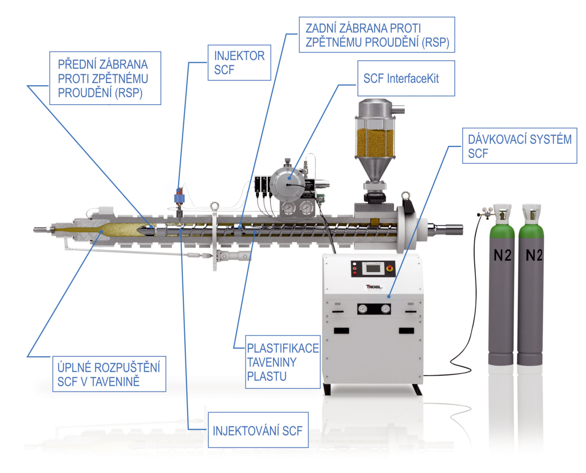 |
| Fig. 1. Plant concept for the MuCell process: Also existing machines can be retrofitted easily. Since the end of 2005, users no longer need to pay license fees for applying this technology |
Strategic Mistakes Corrected
The first breakthrough was made by Trexel Inc., Wilmington, Massachusetts/USA at the end of the 1990’s with the MuCell process using modified and improved technology. Originally invented at the Massachusetts Institute of Technology (MIT) in the late 80’s, the process was initially aimed at extrusion. It was only at the beginning of the year 2000 that interest was focused on injection molding. However, several strategic mistakes prevented a successful propagation of the process: In addition to the costs for the technical equipment, Trexel demanded license fees from users, whereby the amount was determined annually, and was based on throughput. Since the end of 2005, Trexel no longer charges license fees, but this important information has not yet reached all areas in the plastics industry.
Another hindrance was the marketing strategy.Apart from the original focus on extrusion,Trexel initially failed to address the potential users and OEMs. The company targeted plastics processors and moldmakers, although experience shows that these only have limited influence on the project-related processing technology. Consequently, awareness of the new process was mainly restricted to a small circle of insiders. Meanwhile, Trexel has changed their strategy, and has raised the interest of users and OEMs. As one of the first machine manufacturers, KraussMaffei in Munich, Germany, has cooperated with Trexel from the start.Following the joint development of standardized equipment on the machine side, KraussMaffei included complete MuCell system packages in their product range early in 2001.
 |
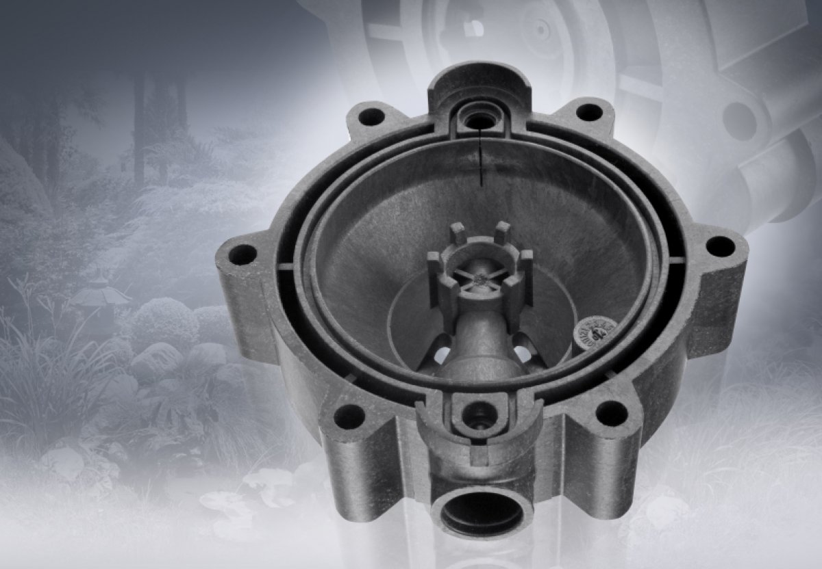
| Fig. 2. By means of physical foaming, this door lock housing can be produced 25 % faster (shorter cycle times) and with 30 % lower clamping force |
Plasticizing Unit With Gas Injector
In simple terms, this type of physical foaming involves injection molding with gas charging. Prerequisite is a fully automated injection molding machine with screw position control and increased injection volume. A plasticizing unit with a specially designed screw is the heart of the system. The gas is injected directly into the plastic melt in the form of a super critical fluid (SCF), from which the screw produces a homogeneous single-phase solution. A nonreturn valve prevents the gas/melt mixture expanding prematurely towards the feed end, and the machine’s shut-off nozzle blocks the melt at the front end. Nitrogen or CO2 is used as propellant (Fig.1).
Important hereby is that the melt pressure in the plasticizing unit – and possibly also in the hot runner system – may not fall below the critical SCF melt pressure during the entire cycle. This is why screw position control (“active back pressure”) is required, which also ensures that the pressure is maintained even when the safety door is open. For the same reason, the machine is operated with a needle valve nozzle, or in the case of hot runner molds with a bolt shut-off nozzle, whereby the nozzle contact force is reduced while the clamping unit is opening. In order to shift the pressure drop – and thereby the beginning of the foaming process – as far as possible toward the end of the filling stage, and to ensure foaming at the end of the flow path, injection must be carried out quickly. Therefore, the machine must have a high injection capacity.
As physical foaming agent, the gas reduces the melt viscosity, which simplifies fast injection. The pressure drop during injection into the cavity triggers the formation of gas bubbles, which cause the melt to be foamed. As opposed to chemical foaming, the MuCell process involves a large number of finely distributed seeds. This fine distribution ensures the formation of many small, equally sized and closed cells with a diameter of less than 100 μm. Within the cross-section of a component, a so-called integral foam structure is created: a foamed core with low density, enclosed in a thin, compact covering layer with higher density. Although the surface is closed, it does not exhibit the quality of a compact injected molding.
 |
| Fig. 3. Cycle times for foaming are reduced due to higher melt viscosity (faster injection), lower holding pressure, and shorter cooling times |
Foaming The Melt Compensates Shrinkage
Foaming of the melt compensates for shrinkage at the mold wall. This permits foaming with a considerably less holding pressure – even without holding pressure in the ideal case. Similarly, the internal mold pressure is significantly lower than with compact injection molding, and lower melt and mold temperatures can also be selected.
All of this – no or very less holding pressure, and lower cooling requirements – reduces the required clamping force by 30 to 50 %, and cuts the cycle time by about 20 % (Figs. 2 and 3). Moreover, the moldings exhibit very low warpage. In most cases, they are completely free of sink marks and air traps. The foaming process is also effective at the end of the flow path, where the holding pressure is often obstructed by freezing of the plastic core. When manufactured on the basis of existing component geometries, foamed molded parts are between 7 and 10 % lighter than their compact injected counterparts. Depending on the geometry, and with a MuCell-compatible component design,weight savings up to 20 % are possible (Fig. 4). In this respect, the process is particularly attractive for new lightweight projects.
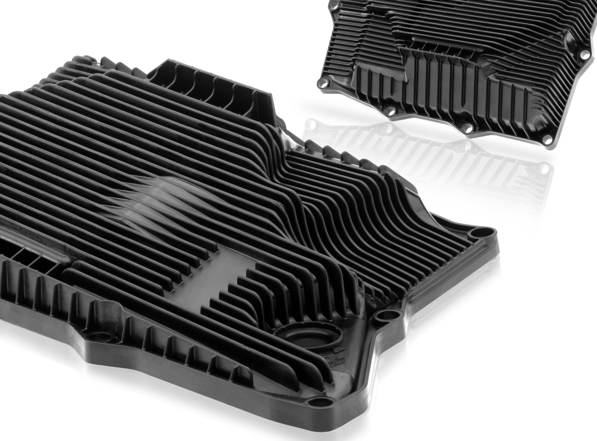 |
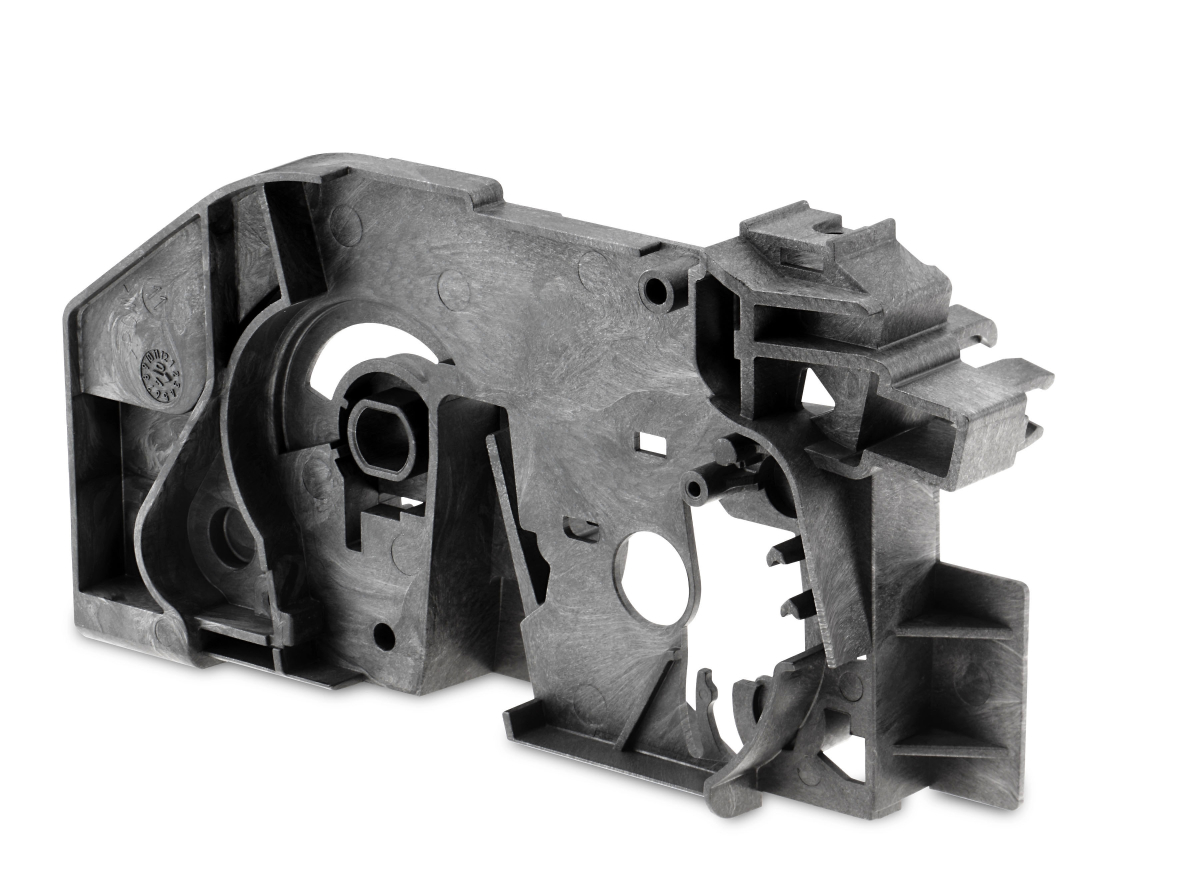
| Fig. 4. Oil pans made of foamed plastic score points against their metal counterparts, thanks to their considerably lower weight and freedom from warp, which ensures unproblematic installation |
Operation is simplified by a special software package. As an integral part of the KraussMaffei MC5 control system or the new MC6, all important parameters can be adjusted, monitored, and displayed centrally. The process values required for calculating the amount of gas, such as SCF flow rate, injector opening time, and weight reduction, can be determined by means of a computer that is part of the system, and are then simply transferred to the parameter settings of the MuCell pages.
The software has a clear structure. Just one operating page shows only the most important parameters, and permits them to be adjusted. Separate pages are provided for adjusting the basic settings, which must usually be entered only once.
Comparison of Chemical and Physical Foaming
Numerous investigations and reports that compare chemical and physical foaming have been prepared in the past,with partially different conclusions. Apart from the component surface quality, physical foaming tended to be slightly better. Regarding homogeneity of cell size and distribution, the MuCell process exhibits clear advantages.Although the process is somewhat complex, it is clearly defined and absolutely reproducible, thanks to the direct gas injection. Foaming agent costs that are at least 80 % lower, are a further advantage.
On the other hand, chemical foaming is very simple, due to the indirect introduction of the foaming agent via a metering unit. However, the process cannot be influenced directly – only indirectly via temperature control and screw speed.
One disadvantage of MuCell plastication is the shortened plasticating zone caused by the middle non-return valve, which can have an effect the required shot weight, and depends on the material used. However, regarding the choice of material, the process is extremely flexible.Nitrogen is used as foaming agent in about 90 % of all applications. Therefore, the process is ideally suited for applications in which subsequent solvent evaporation (fogging) is undesirable.
Investment Costs Pay Off
On the financial side, the situation is quite clear: Although the MuCell equipment involves higher investment cost, the operating costs are significantly lower. The possible savings due to reduced foaming agent costs and lower material consumption lead to an average ROI of six months up to one year (established on a machine with 6,500 kN clamping force).Obviously, the amount of material saved also depends on the size of the molded component.As a rule of thumb, one can assume savings ranging from about 10 % up to almost 20 %. Furthermore, a significantly higher productivity must be taken into account, which is due to the shorter cycle times of up to 20 %.
Like most other special processes, physical foaming pays off especially with large production quantities or high machine utilization. One argument in favor of the latter is the slightly limited application flexibility of the plasticizing unit. Although the special equipment also permits compact molded parts to be produced, the shorter plasticizing zone must be kept in mind. Therefore, in case of a corresponding demand, it is advisable to replace the MuCell with a standard plasticizing unit.
Ongoing Projects
Obviously, the savings in material and the associated weight reductions that are achievable with foam injection molding have a particularly great impact with very large components. In order to support potential as well as existing active users, the plastics processing companies Mürdter, Trexel, and KraussMaffei agreed to cooperate. As a result, the world’s largest injection molding machine for the MuCell process, an MC 5400-17.200 with 54,000 kN clamping force, was commissioned in the Mürdter Technikum in Mutlangen, Germany, at the end of 2011. With this machine, a direct comparison of large compact injected and foamed components is possible for the first time.Moreover, the findings gained during the tests can be implemented directly in the adjacent moldmaking workshop, which saves time and money. The new machine also permits tests with the SGI process (integral foam injection) to be carried out (see box). Proper Group, a processor in the United States has a similar but smaller plant.
For two years already, Kunststofftechnik Wiesmayer GmbH in Neustadt on the Danube, Germany, has been using the MuCell process on a large injection molding machine with 16,000 kN clamping force (type MX made by KraussMaffei). Using tandem technology on this machine, Wiesmayer produces interior supports for doors of the Mercedes ‘E’ class. Because the process requires no holding pressure, the parts exhibit far lower warpage than compact injected components. Because the tandem technology permits one part to be de-molded during the cooling phase of the other part, productivity has been boosted by a factor of 1,6.
Nonetheless,KraussMaffei has continued its research in the chemical foaming process, which is being marketed together with the physical process under the name “CellForm”.
Outlook
Current developments are aimed at improving the surface quality of foamed components. Automakers in particular are hoping for advances to be made here. Raw material suppliers are already developing suitable new materials.Alternatively, grained or eroded surfaces could be considered as a first step.For perfect, possibly high-gloss visible surfaces, a combination with dynamic mold tempering could prove to be suitable, for example with pulse cooling, as presented by KraussMaffei at the Fakuma 2012.
Moreover, combined processes such as foil back injection or in-mold surface decoration are conceivable. Advantageous hereby are the low pressures of the Mu- Cell process. For the production of multi- functional components,physical foaming can also be combined with the multi- component technology. For the production of structural components, sandwich structures using organic sheets are a possible solution. Basically, however, a bright future can be predicted for the MuCell process – not only because of its technical advantages, but mainly because of the resource-saving material consumption.
- autor:
- KUBOU�EK s.r.o.
-

KUBOU�EK s.r.o.
Measuring instruments, injection molding machines, tempering equipment, belt conveyors, cooling systems, mills and granulators, hot runners, dispensers, plastic crushers.
- www.kubousek.cz
- Lidick� 1937, �esk� Bud�jovice
You might also be interested
-

Radiation-crosslinked plastics instead of metal
Cheap and simple production of robust components. High-energy radiation can improve the mechanical, thermal, chemical and tribological properties of plastics to such an extent that they can replace metals in some...
-

OptiXs, s.r.o. - How to laser weld plastics
- 27.03.2024
- Plastics Processing
- Lasers
Laser welding of plastics has several advantages over other joining methods, but its proper implementation requires knowledge of the technology and often benefits from discussion with a knowledgeable equipment supplier early in the product development...
-

Weppler Czech s.r.o. - We offer everything under one roof!
Our company is headquartered in the Czech Republic, where we have built a strong market position and gained the trust of many customers. We are part of the Weppler Group. We specialize in the production of plastic and metal parts using multi-component injection moulding and die-cutting, moulding...
-

Case studies of functional parts for 3D printing by Stepanek3D
- 13.12.2023
- Plastics Processing
- 3D technology
The company Stepanek3D, engaged in various activities in the field of 3D printing, has created case studies for functional parts in this field. Current 3D printing makes it possible in many cases to produce final functional parts with sufficient accuracy and sufficient mechanical...


-

Radiation crosslinking of plastics has high potential for electric cars
BGS Beta-Gamma-Service GmbH & Co. KG. provides comprehensive services in the field of industrial irradiation and optimization of plastic products. Questions about radiation crosslinking of plastics in the automotive industry were answered by Dr. Michal Dan�k, who is a specialist in this...
-

PLASTIKA digitizes production and uses artificial intelligence during control
- 03.11.2023
- Plastics Processing
- Smart factory
- Plastic products
The Krom��� company Plastika, which produces parts for the automotive industry, bets on modern technologies. It deploys a system where production takes place through a terminal. And today's popular artificial intelligence helps with the control that makes sure everything is going as it...
-

The tyranny of the melt flow rate
- 06.09.2023
- Plastics Processing
- Events
- Recycled plastics
The plastics industry faces significant challenges in the coming years between 2025-2030. According to the commitments of the European Plastics Pact, an average of 25-30% recycled plastic must be used in plastic finished products and packaging...

-

Biopolymers: New application possibilities in electronics and electrical technology through radiation crosslinking
Products in the electrical technology and electronics (E&E) industry have to meet high flame retardant standards and often demanding thermal requirements. Polymers available on the market so far do not meet these...
-

BGS: Electron Booster for Electric Vehicles
The conditions in electric vehicles place high demands on the materials used. Therefore, automakers and suppliers must resort to expensive, high-performance plastics. For many applications, cost-effective alternatives are plastics whose properties have been greatly improved by means of treatment...
-

BGS Irradiation Service Days: Virtual trade fair on plastics radiation crosslinking for e-mobility, mechanical engineering and the cable and electrical industries
- 16.09.2022
- Plastics Processing
- Events
- Radiation technologies
BGS Beta-Gamma-Service, specialized provider in the field of plastics radiation crosslinking and plastics radiation sterilization, invites you to the virtual trade fair BGS Irradiation Service Days (ISDbyBGS) for the second time in a...


Branch Dictionary